Home > Honeywell Home > Honeywell Home TH8320R1003-Uv VisionPRO 8000 with RedLINK Multistage Thermostat Installation Guide
Honeywell Home TH8320R1003-Uv VisionPRO 8000 with RedLINK Multistage Thermostat Installation Guide

®
®
VisionPRO Series with RedLINK 2.0
Installation Guide
TM
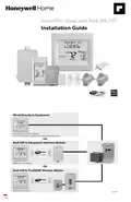
Wired Directly to Equipment
Dual Powered - C Wire or Battery
(C wire or Wire Saver required to use RedLINK accessories)
OR
RedLINK to Equipment Interface Module
TM
2 Wires for Power or
Battery Only (no wires)
OR
RedLINK to TrueZONE Wireless Adapter
TM
2 Wires for Power or
Battery Only (no wires)
M37817

| General | Details |
|---|---|
| Name | Honeywell Home TH8320R1003-Uv VisionPRO 8000 with RedLINK Multistage Thermostat Installation Guide |
| Make | Honeywell Home |
| Language | English |
| Filetype | PDF (Download) |
| File size | 0.64 MB |


Honeywell Home TH2110DH 1 Cool Programmable Digital Thermostat Installation Guide

Honeywell Home DT4R Wireless Room Thermostat User Guide

Honeywell Home N100 Series Non Programmable Thermostat User Guide

Honeywell Home X1N Non Programmable Thermostat Installation Guide

Honeywell Home DT4M Wired Room Thermostat User Manual

Honeywell Home T834 Series Thermostat Owner’s Manual

Honeywell Home M38794 T10 and T10 plus Pro Smart Thermostat with RedLINK Installation Guide

Honeywell Home DT4 Channel Wired Room Thermostat Instruction Manual

Honeywell Home T10 Smart Home Thermostat Instructions

Honeywell Home FocusPRO Smart S200 Series Smart Thermostat User Guide

Honeywell Home TH8320R1003-Uv VisionPRO 8000 with RedLINK Multistage Thermostat Installation Guide Overview
Summary of Contents
- Page 1: VisionPRO Series with RedLINK 2.0 Installation Guide Wired directly to equipment Dual powered - C wire or battery C wire or wire saver required to use RedLINK accessories RedLINK to equipment interface module 2 wires for power or battery only RedLINK to TrueZONE wireless adapter 2 wires for power or battery only
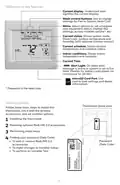
- Page 2: Reference to key features Current display signifies the current display. Mode control buttons are used to change settings for Fan or System Heat/Cool. Menu allows selection of options to set schedules, view equipment status, change IAQ settings, and access installer options. Current status shows system mode, outdoor temperature, and humidity. Current schedule displays desired temperature and schedule status. Indoor conditions indicate indoor temperature and humidity. Alert light is on when an alert message is active or the system is set to Em Heat. microSD card port is used to load settings and dealer information. Getting started includes basic steps to install the thermostat and set installer options. Finding your password (Date Code) is necessary for making changes to Installer Setup and performing an Installer Test.
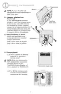
- Page 3: Installing the thermostat For best RedLINK 2.0 performance, mount thermostats at least 2 feet apart. Separate wallplate from thermostat. If your thermostat has a button along the top of the wallplate, press the button on top and pull to remove the wallplate. Mount new wallplate using screws and anchors included. Drill 3/16-in holes for drywall. Drill 7/32-in holes for plaster. Connect power. Insert supplied AA alkaline batteries for primary or backup power. When the thermostat is not used with the Equipment Interface Module or the TrueZONE Wireless Adapter, a C wire is required for RedLINK 2.0. For 24VAC primary power, connect common side of transformer to C terminal.
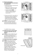
- Page 4: Wire connections for the thermostat should be checked. If the thermostat is wired directly to the equipment, refer to the table and wiring diagrams on the next page. 24VAC is required to connect RedLINK 2.0 accessories. If using an Equipment Interface Module or TrueZONE Wireless Adapter, power the thermostat using Rc and C terminals or with batteries. The relay outputs and inputs on the thermostat do not function when used with an Equipment Interface Module or TrueZONE Wireless Adapter. Insert the coin cell battery with the thermostat removed from the sub-base. On some models, the coin cell battery compartment slides out from the left side of the thermostat. Mount the thermostat on the wallplate. If the thermostat has hinges at the bottom of the wallplate, insert it into the hinges and push the top toward the wall until it snaps together. Updated models do not have hinges; push evenly along the sides and bottom to connect it to the wallplate.
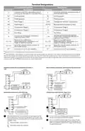
- Page 5: Terminal designations include conventional systems and heat pumps. Common wire connections are specified for cooling transformers. Cooling power and heating power are indicated by terminals Rc and R. The changeover valve for heat pumps is connected to terminal O/B. Backup heat or emergency heat is designated by AUX-E. Compressor stages are identified as Compressor Stage 1 and Compressor Stage 2. Fan relay connections are made through terminal G. Wiring for powered and non-powered humidifiers, dehumidifiers, or ventilators is outlined. Field installation of jumpers is required between R and U1 for certain configurations. U1 terminals are used for low-speed fan control in dehumidification setups.
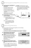
- Page 6: Powering optional RedLINK 2.0 accessories Install batteries in RedLINK 2.0 accessories. If the thermostat is wired directly to the equipment, 24VAC (C wire) is required to connect RedLINK 2.0 accessories. Turn on 24VAC before performing initial setup. Connect gateway to internet and connect to power. Connect RedLINK 2.0 Internet Gateway to router or modem with Ethernet cable (RJ45). Connect gateway’s power cord to an electrical outlet that is not controlled by a wall switch. Initial setup options define the type of system you are installing. Follow prompts on the screen to select the appropriate options. If you are connecting the residential thermostat to the TrueZONE Wireless Adapter, refer to the TrueZONE instructions to link the thermostat and RedLINK 2.0 accessories.
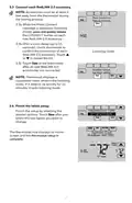
- Page 7: Connect each RedLINK 2.0 accessory. Accessories must be at least 2 feet away from the thermostat during the linking process. Press Connect on New Accessories. While the Press Connect message is displayed, press and quickly release the CONNECT button on each new RedLINK 2.0 accessory. After a short delay, check the thermostat to confirm the connection of each accessory. Touch Done at the thermostat after all new accessories are connected. The thermostat displays a countdown timer while in listening mode. Finish the initial setup by selecting the desired options. The thermostat now displays its Home screen and the setup is complete.
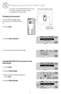
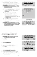
- Page 8: Finding your password (Date Code) You can find the date code on the back of the thermostat. To add or remove RedLINK 2.0 accessories. To make changes to Installer Setup. To perform an Installer Test. Touch Menu. Select Dealer Information. Scroll down to see the Date Code. Enter password (date code) and touch Done. Select Wireless Manager.
- Page 9: Select Add Device. The screen displays “Press Connect on New Accessories.” The thermostat is now in listening mode. Accessories must be at least 2 feet away from the thermostat during the linking process. Press and quickly release the CONNECT button on each new RedLINK 2.0 accessory. After a short delay, check thermostat to confirm the connection of each RedLINK 2.0 accessory. Touch Done at the thermostat after all new RedLINK 2.0 accessories are connected. The thermostat displays a countdown timer while in listening mode. Use a microSD card to save setup time. Touch Menu to access Installer Options. Enter password and touch Done. Follow prompts on the screen to select the desired setup options or to perform an equipment test.
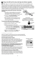
- Page 10: Using a microSD card for setup, data logs, and software upgrades is recommended. Newer microSD cards that exceed 8 MB may have compatibility issues. A microSD card can save setup time by loading various settings to multiple thermostats. Data logs can be saved to a microSD card for troubleshooting. The microSD card is also used for upgrading thermostat software. To load dealer information and new thermostat software, visit the specified website. Connect a microSD USB adapter to your computer to download files. After downloading, insert the microSD card into the thermostat. To use the microSD card in the thermostat, slide the card into the bottom and select the item to load or save. Follow the prompts on the screen to add or save information. When replacing a thermostat, reset the RedLINK 2.0 accessories before connecting them to the new thermostat. Instructions for disconnecting and reconnecting accessories are provided for various devices.
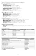
- Page 11: Specifications and replacement parts Operating ambient temperature ranges for various components include: - Thermostat: 32 to 120° F (0 to 48.9° C) - Wireless outdoor sensor: -40 to 140° F (-40 to 60° C) - Equipment interface module: -40 to 165° F (-40 to 73.9° C) Operating relative humidity for components varies: - Thermostat: 5% to 90% (non-condensing) - Wireless outdoor sensor: 0% to 100% (condensing) Physical dimensions for key components are provided: - Thermostat: 4-15/16 x 4-5/8 x 1-1/8 inches - Wireless indoor sensor: 2-7/8 x 1-7/8 x 15/16 inches RedLINK 2.0 communication operates at a frequency of 900 MHz and re-syncs within 6 minutes after AC power resumes. Electrical ratings specify voltage and current ratings for terminals, including: - Voltage: 18 to 30 VAC - Max current rating varies by terminal type. Accessories and replacement parts are listed with part numbers for various components, including: - Equipment interface module - Wireless outdoor sensor Additional accessories include wireless adapters and remote controls for enhanced functionality.
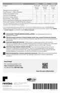
- Page 12: Model numbering includes TH8321, TH8320, and TH8110. Thermostat stages are categorized as 3H/2C HP, 2H/2C, and 1H/1C. Thermostats are suitable for both residential and commercial use. They can be dual powered using a C wire or battery. Onboard humidity sensors are included in some models. The number of IAQ relays varies among models. Thermostats work with optional equipment interface modules and TrueZONE wireless adapters. Power must be disconnected before installation to prevent electrical shock or equipment damage. Special handling may apply for lithium batteries due to perchlorate material. Installation should be performed by a trained technician to avoid damage or hazardous conditions.

iO HVAC CONTROLS Z-2000-T Thermostat Instruction Manual

EPH CONTROLS TRFPi2 COMBIPACK2 Programmable RF Thermostat Instruction Manual

stelpro STZW402 ELECTRONIC THERMOSTAT SMART HOME User Guide
terneo v3G33 Simple Heat Control Thermostat Instruction Manual

Schneider Electric 2290B Programmable Room Thermostat Instruction Manual

Danfoss KP 61 Temperature Switches Thermostat Installation Guide

aube technologies TH115-AF-GA Programmable Thermostat Owner’s Manual
Nexans N-Comfort Kt+ Thermostat Instruction Manual

GREYSTONE TLOSF24X01 TLOS Series Outside Low Limit Thermostat Instruction Manual

ENGO E20i Series Wi-Fi Wireless Internet Thermostat User Guide