Honeywell ATC928 Evohome Connected Multi Zone Room Thermostat Installation Guide


evohome
EN Installation Guide

| General | Details |
|---|---|
| Name | Honeywell ATC928 Evohome Connected Multi Zone Room Thermostat Installation Guide |
| Make | Honeywell |
| Language | English |
| Filetype | PDF (Download) |
| File size | 0.53 MB |


Honeywell T6 Pro Programmable Thermostat User Manual

Honeywell D1-528 Direct Thermostat Installation Guide

Honeywell FocusPRO P200 Programmable Thermostat User Guide

Honeywell RCHT8610WF Series Smart Thermostat Installation Guide

Honeywell T9 Smart Thermostat Installation Guide

Honeywell TH2320WF4011 FocusPRO Smart S200 Series Thermostat User Guide

Honeywell TL116A Thermostat Installation Guide

T10 Pro Smart Thermostat with Redlink Room Sensor

Honeywell TH6320WF2003 Lyric T6 Pro Wi-Fi Programmable Thermostat User Guide

Honeywell RTH9580 Wi-Fi Color Touchscreen Programmable Thermostat User Guide

Honeywell ATC928 Evohome Connected Multi Zone Room Thermostat Installation Guide Overview
Summary of Contents
- Page 1: Page 1
- Page 2: Icon key evohome Controller Single Zone Thermostat Room Temperature Sensor evohome Controller Wall Bracket evohome Controller Table Stand Digital Room Thermostat Radiator Controller Wireless Cylinder Thermostat Wireless Relay Box Underfloor Heating Controller
- Page 3: evohome means more comfort and more control of the heating system. It’s simple to install and easy to use. Devices that need to be connected to the mains electricity supply should be installed by a competent person. Make sure you have all the devices you need for your system. It’s a good idea to carry out all the mains electrical and other wiring work first. Step 1: Wire up the heating system. Step 2: Set up your evohome Controller. Step 3: Power up and bind devices. Step 4: System test. Configuration and modification.
- Page 4: Step 1: Wire up the heating system Connect all mains powered devices to the heating system. Step 2: Set up your evohome Controller Power up the evohome Controller, connect to a WiFi network and follow the on-screen instructions for your system. Step 3: Power up and bind devices Power up all devices, including the battery powered ones, and bind them to the evohome Controller. Step 4: Test the system Check that all the devices are working properly.
- Page 5: evohome communicates using wireless on a robust 868Mhz signal that is unaffected by common remote controls or WiFi. Some devices need mains power or to be connected to external equipment and it's best to wire up these items first to simplify the binding process later in the setup. The evohome controller will give on-screen instructions when these should be powered up. Before you power up your evohome Controller and install the radiator controllers, it's best to install any devices which are mains powered or need specific installation. In this section, Wireless Relay Box (BDR91), Wireless Cylinder Thermostat (CS92), Mixing Valve Controller (HM80), Underfloor Heating Controller (HCE80/HCC80), Opentherm Bridge (R8810).
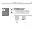
- Page 6: Step 1: Wire up the heating system Wireless Relay Box (BDR91) If you’re fitting a Wireless Relay Box (BDR91) to your boiler, zone valve or sundial valve, turn off at mains and isolate the supply before starting. Mount the Wireless Relay Box on a non-metal surface at least 30cm from your boiler, other wireless devices or metal objects. Release the clip on the bottom to open the front cover. Follow the wiring diagram to connect the Wireless Relay Box to your boiler’s thermostat terminals, zone valve or sundial valve, and to the mains electricity supply. Replace the cover. Refer to boiler instruction to locate the room thermostat terminals, determine if the boiler required a permanent live supply.
- Page 7: Wireless Cylinder Thermostat (CS92) You will need to install the CS92 Transceiver and only one of the two sensors. To fit the CS92 Strap-on Sensor: Cut away a section of cylinder insulation slightly larger than the sensor unit. Clean the exposed cylinder surface. Place the sensor on the cylinder surface and secure it using the fixing strap. Install the CS92 Transceiver in a suitable location close enough for the cable from the sensor to reach. Connect the cable from the sensor to the CS92 Transceiver. Position the sensor from one quarter to a third of the way up the cylinder.
- Page 8: Step 1: Wire up the heating system To fit the CS92 Insertion Sensor Fit in the cylinder immersion well with suitable fittings to provide strain relief and prevent accidental removal. If the sensor doesn’t fit tightly in the immersion well, fill the space with heat-conductive compound to ensure maximum heat transfer. Install the CS92 Transceiver in a suitable location close enough for the cable from the sensor to reach. Manufacturer’s instructions must be followed to ensure compliance with all safety regulations. Connect the cable from the sensor to the CS92 Transceiver. The wires are polarity free, so can be connected in any order. Provide appropriate strain relief to this end of the sensor cable as well.
- Page 9: evohome installation guide Mixing valve controller (HM80), underfloor heating controller (HCE80/HCC80), OpenTherm bridge (R8810) If you’re fitting a mixing valve controller, underfloor heating controller, OpenTherm bridge Refer to the installation instructions supplied with each device
- Page 10: Step 1: Wire up the heating system
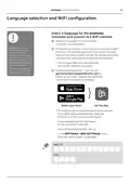
- Page 11: evohome installation guide Step 2: Set up your evohome controller The evohome controller has a guided configuration process to help you set up the zones for a single type of system. For mixed systems, use guided configuration for the larger system then “Add Zones” in the installer menu. To add a stored hot water system, use the guided configuration Stored Hot Water option in the installer menu. The following instructions cover the full configuring process for a zone, but if you are using guided configuration, your evohome controller will give you on-screen instructions to bind the other components. Powering up your evohome controller Language selection and WiFi configuration Set up the evohome controller for your system
- Page 12: Step 2: Set up your Central Controller Powering up your evohome Controller First, power up the evohome Controller. Remove the cover, remove the battery tab and replace the cover. Your evohome Controller comes with rechargeable batteries which are pre-charged allowing you to set up the system while off the table stand or wall bracket. Once the batteries are fully charged, the evohome Controller can be easily removed from the table stand or wall bracket for ease of programming. After 30 minutes the evohome Controller will emit a beep to indicate that it should be replaced on the stand or wall bracket. Place the evohome Controller on the table stand or wall bracket for normal use. Only use the AA rechargeable batteries provided.
- Page 13: evohome installation guide Select a language for the evohome controller user interface. Follow the on-screen instructions to connect to a WiFi network. This enables automatic setting of the date and time for your location. If you don't require remote access, you can skip the WiFi configuration. WiFi can be configured later in the SETTINGS > WIFI SETTINGS menu. Instruct the homeowner/user to visit getconnected.honeywellhome.com to create an account. The homeowner will need the MAC ID and CRC to register the evohome Controller. The MAC ID and CRC can be found on a label behind the front cover of the evohome Controller. They can also be found on screen during the WiFi set-up or in the SETTINGS > WiFi SETTINGS menu after set-up has been completed.
- Page 14: Step 2: Set up your central controller Set up the evohome controller for your system. Choose the correct option for the system you’re installing. For a Connected Pack and no additional un-bound devices, press ‘Home’ and go to Step 4: System test on page 29. For a Connected Pack plus additional un-bound devices, press ‘Installation Menu’ to add the un-bound devices. For an un-bound evohome Controller plus additional un-bound devices, press ‘Guided Configuration’ to add the un-bound devices. A Connected Pack contains devices which are already bound to the evohome Controller. Choosing Guided Configuration will delete the binding from the evohome Controller. The Wireless Relay Box (BDR91) in a Connected Pack is bound as a boiler controller. If you intend to use it as a Zone Valve or S-Plan/Y-Plan (Sundial) Valve controller, the binding must be cleared from the Wireless Relay Box first.
- Page 15: evohome installation guide Step 3: Power up and bind devices If you bought a Connected Pack only, your devices are already bound. If you bought an unbound evohome Controller, follow the instructions on your evohome Controller screen to put the devices into binding mode. If you bought a Connected Pack plus other unbound devices, power up all devices and bind them to the evohome Controller using the Installation Menu. It may be easier to power up and bind some devices while they’re close to the evohome Controller. When you bind a device to the evohome Controller, the devices permanently store the connection and there should never be a need to rebind them again. In this section: Radiator Controllers (HR92), Wireless Cylinder Thermostat (CS92), Wireless Relay Box (BDR91) to control a Boiler, OpenTherm Bridge (R8810), Wireless Relay Box (BDR91) to control a Zone Valve, Radiator Controller (HR80), Underfloor Heating Controller (HCE80 or HCC80), Mixing Valve Controller (HM80).
- Page 16: Step 3: Power up and bind devices Power up and bind Radiator Controllers If you are not following guided configuration, follow these steps on your evohome Controller display first. Bind the Radiator Controllers (HR92). Remove the circular top cover. Open the battery clip and insert the AA batteries supplied. Press and hold ‘Settings’ for 3 seconds. You should receive a success message on the evohome Controller. You must repeat these steps for each radiator controller. Press the green tick button for a further action. Type a name for the new zone and press the green tick.
- Page 17: Install the radiator controllers (HR92). Locate the room (zone) for the radiator controller. Slide the locking mechanism to the unlock position. Remove the adaptor from the bottom of the controller. Unscrew the black wheel fully anti-clockwise. Remove any existing control on the radiator valve. Screw the white end of the adaptor on to the radiator valve. Push the controller fully on to the adaptor with the screen facing towards you. Slide the locking mechanism to the locked position.
- Page 18: Step 3: Power up and bind devices To control a stored hot water system you first need to bind the CS92 Transceiver and then bind the Wireless Relay Box (BDR91) that is controlling the hot water valve. If you are not following guided configuration, follow these steps on your evohome Controller display first. Power up and bind the CS92 Transceiver. On the CS92 Transceiver, press and hold “Settings” for 3 seconds. Remove the CS92 Transceiver cover, pull out the battery tab and replace the cover. Press the green tick. On the CS92 Transceiver, press and hold the button for 5 seconds. The green light should come on and the red light should flash. You should receive a success message on the evohome Controller (if not go back and re-bind).
- Page 19: evohome installation guide To bind the Wireless Relay Box (BDR91) controlling the hot water valve. On the Wireless Relay Box, press and hold the button for 15 seconds to clear any previous binding data. You may need to refer to the wiring diagrams in the Appendix. Press and hold the button again for 5 seconds. On the evohome Controller press the green bind button. You should receive a SUCCESS message on the evohome Controller. The Wireless Relay Box in a Connected Pack is bound as a boiler controller. If you intend to use it as a S-Plan/Y-Plan Valve controller, the binding must be cleared from the Wireless Relay Box first.
- Page 20: Step 3: Power up and bind devices Wireless Relay Box (BDR91) to control a boiler Power up and bind a Wireless Relay Box Make sure the Wireless Relay Box (BDR91) is wired to the boiler and powered up. If you are not following guided configuration, follow these steps on your evohome Controller display first: To bind the Relay Box: Press and hold the button for 15 seconds to clear any previous binding data. Press and hold the button again for 5 seconds. On the evohome Controller press the green bind button. You should receive a success message on the evohome Controller.
- Page 21: OpenTherm Bridge (R8810) Power up and bind an OpenTherm evohome Controller Bridge (R8810) to control an OpenTherm boiler. Make sure the OpenTherm Bridge (R8810) is wired to the boiler and powered up. To bind the OpenTherm Bridge, press and hold ‘Settings’ for 3 seconds. Press and hold the button for 15 seconds (until the red LED blinks rapidly) to clear any previous binding data. Press the green tick. Press and hold the button again for 5 seconds (until the red LED blinks slowly). On the evohome Controller press SYSTEM DEVICES. Press BOILER CONTROL. Press OPENTHERM BRIDGE. You should receive a SUCCESS message on the evohome Controller.
- Page 22: Step 3: Power up and bind devices Wireless Relay Box (BDR91) to control a Zone Valve Power up and bind a Wireless Relay Box Make sure the Wireless Relay Box (BDR91) is wired to the Zone Valve and powered up. If you want to control the zone temperature with the evohome Controller, press YES. To bind the Digital Room Thermostat (DTS92), follow specific steps including pressing and holding “Settings” for 3 seconds. You should receive a SUCCESS message on the evohome Controller after binding. To bind the Single Zone Thermostat (Y87RF), press and hold on the left touch zone for approximately 10 seconds. Turn the dial clockwise until a flashing 'Co' is displayed. Press the left touch zone once to send the binding signal to the evohome Controller. If not successful, go back and re-bind.
- Page 23: To bind the Room Temperature Sensor (HCW82 or HCF82), press the bind button on the bottom right hand corner of the unit once. The red LED light will flash. You should receive a SUCCESS message on the evohome Controller. If not, go back and re-bind. For the Wireless Relay Box (BDR91), press and hold the button for 15 seconds to clear any previous binding data. Press and hold the button again for 5 seconds until the red LED blinks slowly. The Wireless Relay Box in a Connected Pack is bound as a boiler controller. If you intend to use it as a Zone Valve controller, the binding must be cleared from the Wireless Relay Box first. On the evohome Controller, press the green bind button. You should receive a SUCCESS message on the evohome Controller. If not, go back and re-bind.
- Page 24: Step 3: Power up and bind devices Power up and bind a Radiator Controller If you want to control the zone temperature with your evohome Controller, press YES, otherwise press NO and bind the sensor. On the HR80, you need to bind the sensor and actuator separately. Press and hold “Settings” for 3 seconds. Power up the Radiator Controller. Press the green tick to bind the sensor. Type a name for the new zone and press the green tick. The Radiator Controller screen should briefly show a flashing RF icon then SYNC when successful.
- Page 25: To bind the actuator, press the bind button on the Radiator Controller. The screen should show a flashing RF icon. On the evohome Controller, press the green bind button. Check that all the Radiator Controllers display SYNC. If a Radiator Controller does not display SYNC and the flashing RF icon remains, press back on the evohome Controller and press the green bind button again. Press the next arrow on the evohome Controller.
- Page 26: Step 3: Power up and bind devices Power up and bind an Underfloor Heating Controller (HCE80 or HCC80). If you want to control the zone temperature with your evohome Controller, press YES; otherwise, press NO and bind a sensor. Follow these steps on your evohome Controller display once the underfloor heating controller and sensors have been fitted. To bind the Digital Room Thermostat (DTS92), press and hold the power button for 2 seconds to put the unit into standby. You need to install a sensor (HCW82, HCF82, DTS92) in each zone controlled by the underfloor heating controller and bind it to the evohome Controller. You should receive a SUCCESS message on the evohome Controller; if not, go back and re-bind. You need to repeat this process for every zone that uses underfloor heating. Make sure the zone you’re adding on the evohome Controller corresponds to the correct underfloor heating zone.
- Page 27: To bind the Room Temperature Sensor (HCW82 or HCF82), press the bind button on the bottom right hand corner of the unit once. The red LED light will flash. You should receive a SUCCESS message on the evohome Controller. All of the remote room sensors will automatically exit from their binding menu after a short period. If not, go back and re-bind.
- Page 28: Step 3: Power up and bind devices Press and hold the bind button until the bind light turns solid yellow and the zone number light flashes. There are two versions of HCE80/HCC80. If the zone light is flashing green, follow the single stage bind process. If the zone light is flashing red, follow the two stage bind process. On the evohome Controller, press the green bind button. When the zone light turns solid yellow, the binding is successful for the zone. Press forward on the evohome Controller to complete the binding for this zone. If binding more zones, repeat the process from the sensor binding step. Press the bind button twice on the Underfloor Heating Controller for the next zone. When the zone light turns solid green, the binding is successful for that zone.
- Page 29: Mixing Valve Controller (HM80) A Mixing Valve Controller should only be fitted by a qualified fitter. Unless you’re using the evohome Controller as a sensor, you need to install a sensor before binding the controller to the evohome Controller. Follow these steps on your evohome Controller display once the Mixing Valve Controller and sensor have been installed. To bind the Digital Room Thermostat (DTS92), press and hold “Settings” for 3 seconds. Press the power button for 2 seconds to put the unit into standby. Press the up and down arrows together for 3 seconds – it should say INst. Press ADD ZONE. You should receive a SUCCESS message on the evohome Controller (if not go back and re-bind).
- Page 30: Step 3: Power up and bind devices To bind the Room Temperature Sensor (HCW82 or HCF82), press the bind button on the bottom right hand corner of the unit once. You should receive a SUCCESS message on the evohome Controller (if not go back and re-bind). Press and hold both buttons on the Mixing Valve Controller for 4 seconds until the red light flashes. On the evohome Controller press the green bind button. A Mixing Valve Controller will not provide a heat demand to the boiler. If you do want this zone to provide a heat demand, simply change the heating type from 'MIXING VALVE' to 'ZONE VALVES' once the Mixing Valve controller is bound. There's no need to re-bind any device – The Mixing Valve Controller will still operate as intended.
- Page 31: Step 4: System test Now that all the devices are bound to your evohome Controller and installed in their final locations, check that the system works properly and that all the devices are responding to commands from the evohome Controller. You can perform a simple functional check of the heating system by overriding the temperature of each zone to their minimum and maximum while listening for a response from the radiator (or zone) controllers and boiler. To save power, the battery devices only communicate with the evohome Controller every four minutes; therefore, the system may not respond immediately to a manual temperature change. In this section Advanced RF communication check Mains powered wireless devices Battery powered wireless devices
- Page 32: Step 4: System test Advanced RF communication check To check the RF signal strength between the wireless devices and the evohome Controller, go to RF COMMS CHECK in the evohome Controller Installer Menu and test each wireless device. To save power, the battery devices only communicate with the evohome Controller every four minutes; therefore, the system may not respond immediately to a manual change. Mains powered devices do not need to be put into test mode and will automatically respond to the test message sent from the evohome Controller. The Relay Box will flash the red LED from 1 flash (poor) to 5 flashes (excellent) – no flashing means the Relay Box has not received a test signal from the evohome Controller. The Underfloor Heating Controller will flash the green LED for the zone you are testing from 1 flash (poor) to 5 flashes (excellent) – no flashing means the Underfloor Heating Controller has not received a test signal from the evohome Controller.
- Page 33: Battery powered devices need to be put into test mode to send and receive a test signal. To test the radiator controller (HR92), press the button to display the zone name. Press and hold the button again for 5 seconds until the display says BIND. Turn the dial to display RF CHECK. Press the button, and the display should flash CHECKING. Press the button again, and the display will flash SIGNAL, showing a signal strength bar rated from 1 (poor) to 5 (excellent). A rating of 0 means the radiator controller has not received a test signal from the evohome controller. To exit test mode, turn the dial to exit and press the button. The test mode will also exit automatically after 10 minutes.
- Page 34: Step 4: System test Advanced RF communication check continued Radiator Controller (HR80) Separate the Radiator Controller from the adaptor on the radiator. Turn the adjustment dial clockwise (approx two full rotations) until TEST is displayed. The evohome Controller will display the signal strength (poor to excellent). Nothing on the evohome Controller display means the Radiator Controller has not received a test signal. To exit test mode remove and reinsert the batteries from the Controller. It will exit automatically after 5 minutes.
- Page 35: Digital Room Thermostat (DTS92) Put the Room Thermostat into standby mode. Press up and down together for 3 seconds. Press down once, the display should say CONT. Press down for 3 seconds, the display should say TEST. The evohome Controller will display the signal strength. The Room Thermostat will display a signal strength rating from 1 (poor) to 5 (excellent). 0 means the Room Thermostat has not received a test signal. To exit test mode, press off on Room Thermostat for 5 seconds. It will exit automatically after 10 minutes.
- Page 36: Step 4: System test Advanced RF communication check continued Room Temperature Sensor (HCF82 or HCW82) Remove the cover from the sensor. Press and hold the bind button for approximately 30 seconds until the red LED goes off. The red LED will flash each time it sends a test message. The evohome Controller will display the signal strength (poor to excellent) – no flashing means the Temperature Sensor has not received a test signal from the evohome Controller. To exit test mode, press the bind button on the Temperature Sensor. It will exit automatically after 5 minutes.
- Page 37: Wireless Cylinder Thermostat (CS92A) Press the button on the Cylinder Thermostat transceiver for 5 seconds. The green light should come on. If it doesn’t, reinsert the batteries and try again. The evohome Controller will display the signal strength (poor to excellent). The transceiver should flash the red LED from 1 flash (poor) to 5 flashes (excellent). No flashing means the transceiver has not received a test signal from the evohome Controller. To exit test mode press the button on the transceiver.
- Page 38: Step 4: System test
- Page 39: evohome installation guide Configuration and modification Once you’ve completed these steps you’re ready to start using your evohome system. You can also make parameter adjustments in the evohome Controller to match the exact requirements of the heating system. The operation and functions of each zone can also be adjusted. These can be found in the Installer Menu. Components can be added or replaced by editing the zones or system in the Installer menu. Parameters and control features Configuring a zone with multiple rooms Adding or replacing components in an existing system
- Page 40: Configuration and modification Parameters and control features Once you’ve completed these steps you’re ready to start using evo. The user guide gives you instructions for personalising the settings on the evohome Controller. You can also make parameter adjustments on your evohome Controller to match the exact requirements of the heating system. These can be found in the Installer Menu. To create a multiple room zone, add a new zone and bind the radiator controllers for all the rooms. Room temperature sensing is done by the radiator controllers. A multiple room zone does not support separate remote temperature sensors. Go to the parameters menu and select multiple room zone. Edit an existing zone's parameters to allow bound radiator controllers to work independently.
- Page 41: Adding or replacing components in an existing system To add or replace a zone device such as a radiator controller or temperature sensor. If the device you are replacing is no longer required in the system, remove the power as it may still try to communicate with the system. On the evohome Controller press and hold “Settings” for 3 seconds. Press ZONE CONFIGURATION. Select the required zone. Press RF DEVICE BINDING then follow the instructions to bind the device. To replace a system device such as a wireless relay box, system valve, or hot water component. Press SYSTEM DEVICES. Select the type of device and follow the instructions to bind.
- Page 42: Configuration and modification
- Page 43: Installation guide for evohome includes an appendix with heating system schematics and wiring diagrams. This section features sample evohome systems and detailed wiring diagrams. Safety information is also provided along with technical data for the evohome controller.
- Page 44: Appendix Sample evohome systems The evohome Controller is the sensor for the whole home which is controlled to the same time and temperature schedule. This system also includes wireless connectivity, which is available for any configuration. There are two zone valves − one for stored hot water and one for central heating. The valves open when needed. The boiler is operated via a wired junction box. If a system has been set up and the Wireless Relay Boxes are moved to a new function, the relay binding must be cleared or it will continue to carry out its original function.
- Page 45: evohome installation guide Honeywell Home Y plan three-port mid-position valve The operation is identical to the S plan but it uses a single three-port or mid position valve. If a system has been set up and the Wireless Relay Boxes are moved to a new function, the relay binding must be cleared or it will continue to carry out its original function. Stored hot water and zoned heating system needs HR92s or other zoning solutions for the radiators.
- Page 46: Appendix Wiring diagrams Connecting a wireless relay box to a basic boiler The relay powers the boiler live input. Boiler that requires a permanent live This can be used for boilers with low voltage or 230VAC room thermostat inputs. Remove link at boiler if fitted. If the boiler has an inbuilt timer leave this on constant.
- Page 47: evohome installation guide Two-port zone valve Connecting a two port zone valve Motor Neutral Motor Live End switch (if used) Permanent Live If connecting a two port zone valve with an unvented cylinder connection for a high limit thermostat, the 'L' permanent live feed must be broken when high limit cutout activates on the insertion thermostat. Wiring an OpenTherm Bridge to an OpenTherm boiler. Opentherm equipped boiler Opentherm input on the boiler only. Do not connect to the room thermostat terminals.
- Page 48: Appendix Wiring diagrams continued Two port valves with a wired boiler. If a wireless boiler relay is used, the Grey, Orange wire and feed to pump and boiler are not required. S Plan: 2 two-port valves with a wired boiler.
- Page 49: evohome installation guide Mid position (3 port) valve Y Plan: Three-port mid position valve with a wired boiler Yellow: Earth wire Blue: Motor neutral White: Heating relay Grey: Hot water relay Orange: End switch (if used) In wired system, this typically feeds the boiler. When a wireless boiler relay is fitted, the end switch is not required.
- Page 50: Appendix Safety information This product has been designed for applications as described within this document. For use outside of the scope as described herein, refer to Resideo for guidance. Caution: Isolate power supply and make safe before wiring the unit to prevent electric shock and equipment damage. Installation should be carried out by a competent person. Location of device Evohome Controller should be installed in an open space for best performance as it is a radio frequency device. Take care to dispose of this product and any packaging or literature in an appropriate way. For the best temperature control performance the evohome Controller should not be placed near heat or cool sources. At the end of the product life dispose of the packaging and product in a corresponding recycling centre. This product and its associated documentation and packaging are protected by various intellectual property rights belonging to Resideo Inc and its subsidiaries. Resideo reserves the right to modify this document, product and functionality without notice.
- Page 51: evohome installation guide Controller technical data Power supply specifications include input and output voltage details. Room unit power supply input is 5V. Low voltage cable length is specified for different gauges. Battery type is rechargeable AA 1.2V NiMH. RF communication operates within the ISM band. RF communication range is 30m in a residential building environment. Wireless LAN standards include IEEE 802.11b,g,n. Operating temperature ranges from 0 to 40ºC. Storage temperature ranges from -20 to +50°C.
- Page 52: evohome is designed to convert a system with single zone pipework into a multi zone system, resulting in optimal control and comfort combined with maximum energy saving.

Sygonix SY-6052180 Wi-Fi Thermostat Instruction Manual

TROLEX TX2010 Surface Thermostat Instruction Manual

HELTUN HE-HT01 Heating Thermostat User Guide

GENERAL LIFE Senna 270 Digital Room Thermostat User Manual

STELPRO ST252NPFF Non-Programmable Electronic Thermostat Owner’s Manual

WATTS IOM-T-564 tekmar Invita WiFi Thermostat Instruction Manual

Danfoss KPS 76 Pressure Switch and Thermostat Installation Guide

Network Thermostat X5-WIFI Smart Touchscreen Thermostat Instruction Manual

EMOS P56201BUF Floor Heating Thermostat User Guide

sensi 1F76U-22WFB Series Lite Smart Thermostat Installation Guide