
Home > GE Appliances > GE APPLIANCES RAK190V Energy Management Thermostat Owner’s Manual
GE APPLIANCES RAK190V Energy Management Thermostat Owner’s Manual












INSTALLATION INSTRUCTIONS
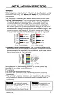
WIRING
Refer to equipment manufacturer’s instructions for specific system wiring
information. After wiring, see INSTALLER MENU for proper thermostat
configuration.
This thermostat is capable of two different wiring communication types:
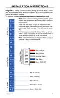
1) 2-Way Communication: This communication may not be available
for all single speed compressor models. This is the preferred form
of communication for our variable speed compressor models. This
communication protocol provides temperature and humidity data to
the variable speed unit to optimize operation. Wiring to the unit will be
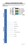
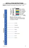
made with a 4 or 5 wire connector. If your unit came with a 5 pin/5 wire
connector, please see Diagram 2. Otherwise, please use the 5 pin/4
wire connector included with this thermostat and refer to Diagram 1.
5 Pin / 5 Wire Connector
5 Pin / 4 Wire Connector
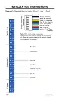
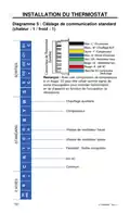
2) Standard (1-Way) Communication: This is conventional thermostat
thermostat communication where the thermostat provides only relayed
signals for the unit to respond to. For this method, wiring to the unit will
be completed using an 8 pin connector:
Black - C - Common
White - W - AUX Heat
Yellow - Y - Compressor
Blue - B - Reversing Valve
Green - GH - High Fan
Tan - GL - Low Fan
Red - R - 24V AC
Light Blue -Y2-2nd Stage
Compressor
8 Pin Connector
Wiring diagrams on the following pages are for typical systems and
describe the thermostat terminal functions.
Precautions
• Do not exceed the specification ratings.
• All wiring must conform to local and national electrical codes and
ordinances.
• This control is a precision instrument, and should be handled carefully.
Rough handing or distorting components could cause the control to
malfunction.
WARNING
CAUTION
Do not use on circuits exceeding
To prevent electrical shock
specified voltage. Higher voltage will damage control
and could cause shock or fire hazard.
Do not short out terminals on primary control to test.
Short or incorrect wiring will burn out thermostat and
could cause personal injury and/or property damage.
and/or equipment damage, disconnect
electrical power to system, at main fuse or
circuit breaker box,until installation is complete.
31-5000842 Rev. 1
5

| General | Details |
|---|---|
| Name | GE APPLIANCES RAK190V Energy Management Thermostat Owner’s Manual |
| Make | GE Appliances |
| Language | English |
| Filetype | PDF (Download) |
| File size | 0.39 MB |
 (1 votes, average: 5.00 out of 5)
 Loading...

GE APPLIANCES RAK160W2 Wireless Thermostat User Manual

GE APPLIANCES RAK190V 2 Way Energy Management Thermostat Instruction Manual

GE APPLIANCES RAK150VF2 Digital Wall Thermostat Instruction Manual

GE APPLIANCES THERMOSTAT Owner’s Manual


Fantini Cosmi CH180-230V Touch Screen Programmable Thermostat Instructions

telethings TELESWITCH – 2L Smart LoRaWAN Thermostat User Manual

Danfoss ECtemp Next Plus Electronic Intelligent Timer Thermostat Installation Guide

Wengart WG603 Home Smart Thermostat User Guide

ENSTO ECO16BTD Floor Heating Thermostat User Guide

Honeywell TH8000 Vertical Non Programmable Thermostat Installation Guide

BOSCH BTH-RM Room Thermostat II User Manual

PRO1 T755 Heat 2 Cool Dual Fuel Thermostat User Manual

Stiebel Eltron RTA-3000 S2 Thermostat Installation Guide

GENERAL LIFE SOLARA 300S RF Wireless Room Thermostat User Manual