Home > GE Appliances > GE APPLIANCES RAK190V 2 Way Energy Management Thermostat Instruction Manual
GE APPLIANCES RAK190V 2 Way Energy Management Thermostat Instruction Manual
PTAC Direct Sales, Inc.
185 S. Kimball Ave. Suite 130
Southlake, TX 76092
877.454.7822 (T)
INSTALLATION INSTRUCTIONS
RAK190V
SPECIFICATIONS ..............................2
INSTALLATION INSTRUCTIONS
WIRING...........................................5
INSTALLER MENU .......................10
USING THE THERMOSTAT
OVERVIEW...................................14
TROUBLESHOOTING.......................15
RESETTING...................................15
WARRANTY..................................... 17
FCC STATEMENT ............................18
31-5000842 Rev. 0 09-23
| General | Details |
|---|---|
| Name | GE APPLIANCES RAK190V 2 Way Energy Management Thermostat Instruction Manual |
| Make | GE Appliances |
| Language | English |
| Filetype | PDF (Download) |
| File size | 0.37 MB |

GE APPLIANCES RAK160W2 Wireless Thermostat User Manual

GE APPLIANCES RAK150VF2 Wall Thermostat Instruction Manual

GE APPLIANCES RAK190V Energy Management Thermostat Owner’s Manual

GE APPLIANCES RAK150VF2 Digital Wall Thermostat Instruction Manual

GE APPLIANCES THERMOSTAT Owner’s Manual

GE APPLIANCES RAK190V 2 Way Energy Management Thermostat Instruction Manual Overview
Summary of Contents
- Page 1: Installation instructions Specifications Wiring Installer menu Using the thermostat overview Troubleshooting Resetting Warranty FCC statement
- Page 2: Specifications Electrical rating: 24 VAC (18-30 VAC), 1 amp maximum per output, 4 amp maximum total load. Setpoint range: 60° to 85° F (16° to 29° C). Operating ambient: 40º F to 99º F (4º C to 37º C). Occupancy sensor range: 5 meters, 109.6 degrees x 109.6 degrees. Humidity range/accuracy: 0 to 95% operating humidity range, +/- 5% accuracy. Shipping temperature range: -30°F to +150°F (-34° to +65°C). Thermostat dimensions: 3.9” H x 5.4” W x 1.03”. Mercury notice: This product does not contain mercury but may replace a product that does. Thermostat applications: Maximum stages heat/cool include single stage cooling and one or two stage heating. Two-way communication with select GE appliance products.
- Page 3: Installation instructions Electrical shock hazard — Turn off power by unplugging the unit or by removing the fuse or switching the appropriate circuit breaker to the OFF position before removing the existing thermostat. Package contents/tools required: Package includes thermostat base, thermostat, screws, and wall anchors. Tools needed include a hammer, screwdriver, and putty. To remove existing thermostat: Turn off power to heating and cooling system by removing the fuse or switching off the appropriate circuit breaker. Remove cover of old thermostat to expose the wires. Remove wires from wire terminals, noting which color wires are attached to each terminal. Remove existing thermostat base from wall. Refer to the following section for instructions on how to install this thermostat.
- Page 4: Installation instructions for the thermostat must conform to local and national building and electrical codes and ordinances. Mount the thermostat about five feet above the floor and avoid placing it on an outside wall, in direct sunlight, behind a door, or in areas affected by a vent or duct. Turn off power to the heating and cooling system before installation. Loosen the screw on the bottom of the thermostat assembly to remove it from the base. Mark the placement of the mounting holes with the base level against the wall. Use a hammer to tap supplied anchors into the mounting holes. Seal the hole for wires behind the thermostat with non-flammable insulation or putty. Insert stripped wires into matching wire terminals and ensure they do not touch other wires. Replace the thermostat by snapping it in place and tighten the bottom screw. Test the thermostat operation in all modes, including fan only, cooling, heating, and both fan speeds.
- Page 5: Installation instructions Refer to equipment manufacturer’s instructions for specific system wiring information. After wiring, see installer menu for proper thermostat configuration. Wiring table shown are for typical systems and describe the thermostat terminal functions. Do not exceed the specification ratings. All wiring must conform to local and national electrical codes and ordinances. This control is a precision instrument and should be handled carefully. Do not use on circuits exceeding specified voltage. Do not short out terminals on primary control to test. To prevent electrical shock and/or equipment damage, disconnect electrical power to system until installation is complete.
- Page 6: Installation instructions provide essential guidance for setting up the system. 2-way communication wiring involves a 5-wire setup. 2-way communication allows equipment to share temperature and humidity data for optimized performance. A link icon will appear on the thermostat when a successful 2-way connection is established. For make-up air models, enable mode “E” in the auxiliary controls to deliver make-up air only when a room is occupied. Colors mentioned in the diagram correspond to the leads on the Zoneline 2-way connector. Red indicates R – 24V AC. Black represents Common. Blue signifies Data A+. White/Blue denotes Data B-. Brown indicates RS485 GND.
- Page 7: Installation instructions Standard communication wiring (3 heat / 2 cool), factory default Aux heat Compressor Reversing valve High fan Low fan 2nd stage compressor 24V AC Common
- Page 8: Installation instructions provide essential guidance for setting up the system. The diagram illustrates standard communication wiring for a two heat, one cool configuration. In a single stage compressor configuration, Y2 can serve as an occupancy out signal. This signal can control make-up air delivery based on occupancy if needed. Auxiliary heat and compressor reversing valve are part of the system setup. High and low fan settings are included in the configuration. An optional occupancy out signal is available. The system operates on 24V AC. Common wiring connections are necessary for proper functionality. Refer to the revision number for the latest updates.
- Page 9: Installation instructions provide guidance on standard communication wiring for a heat and cool system. The document notes that with a single stage compressor configuration, Y2 can serve as an occupancy out signal. This signal can control make-up air delivery based on occupancy if needed. The wiring includes connections for auxiliary heat, compressor, and fan settings.
- Page 10: Installation instructions provide guidance on accessing the installer menu. To access the installer menu, turn the thermostat off using the power button. While the thermostat is off, press and hold the mode and + button for 2 seconds until Setup Mode appears on the display. In the menu, the + / – buttons change the setting selection. The mode button advances to the next menu item. The fan button returns to the previous menu item. The power button saves changes and exits the menu. After two minutes of inactivity, the menu times out and returns to the power off screen. An indicator confirms that you are in setup mode. Two small digits represent the menu item selection, while two large digits represent the setting selection.
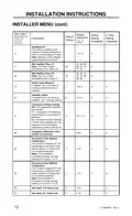
- Page 11: Installation instructions provide essential setup guidance. The installer menu includes various settings for unit configuration. Menu items allow for adjustments to operational parameters. Current hours and minutes can be set for scheduling energy savings. Fan mode options include auto and continuous settings. The unit can be identified as a heat pump or not. Reversing valve type and compressor stages are configurable. Heating and cooling differentials determine stage activation. Auto changeover can be enabled for mode selection. Default settings and availability for each option are specified.
- Page 12: Installation instructions provide essential setup guidance. The installer menu includes various settings for configuration. Deadband is an offset added to cooling and heating differential in autochangeover mode. Min cooling temperature must not exceed the max heating temperature setting. Max heating temperature cannot be lower than the min cooling temperature setting. Room temperature offset calibrates the room temperature reading if needed. Humidity offset calibrates the room humidity reading if necessary. Occupancy energy savings settings determine if temperature setbacks are allowed. Occupancy response time is measured in tenths of a second. Occupancy cool and heat setback temperatures define allowable temperature drifts when no occupants are detected.
- Page 13: Installation instructions Occupancy status timer maintains occupancy status for a specified number of minutes after an event occurs. Scheduled energy savings start time allows selection of when occupancy-driven setbacks are permitted. Scheduled energy savings stop time allows selection of when occupancy-driven setbacks are no longer permitted. Device 1 controls an external relay wired to the O1 output on the terminal block. Device 2 controls an external relay wired to the O2 output on the terminal block. Defaults reset option restores all programming defaults after leaving the installer menu.
- Page 14: Using the thermostat requires familiarity with its features, display, and button operations. The thermostat buttons include options for power, fan selection, mode selection, lower setpoint, and raise setpoint. Fan selection has two-way options: low and high, which can operate in auto or continuous modes. The display shows the selected setpoint and a two-way communication indicator, which indicates connection status. Mode selection includes heat, cool, and fan options, with autochangeover available if enabled in the settings. Auto must be enabled in setting 15 to be an available option for mode selection. There are eight wire options for fan selection, which include auto low, auto high, low, and high. A solid link indicates a connected status, while a blinking link signifies a connection issue. Understanding these features is essential for effective thermostat operation. Familiarity with the thermostat buttons and switches is crucial before use.
- Page 15: Troubleshooting No display: Press power button to ensure thermostat isn’t off. Check for 24 VAC; display is blank when 24 VAC is not present. System fan does not come on properly: Verify that wiring is correct. All thermostat buttons are inoperative: Verify that 24 VAC is present; unit will not operate when 24 VAC is not present. Thermostat turns on and off too frequently: Adjust temperature differential. Fan runs continuously: Check fan selection. If set to High or Low in 8-wire mode, fan will run continuously. Compressor doesn’t run or turns off immediately when changing function or setting: There is a 3 minute time delay and a 3 minute minimum run time for the compressor. Fan doesn’t run or turn off immediately when changing function or setting: This is normal; on some models, the fan may have a minimum run time/off time delay. Resetting the thermostat or thermostat settings: To conveniently reset only the user settings back to factory defaults, see setting 99 in the Installer Menu. Warning: This product contains a chemical known to the state of California to cause cancer and birth defects and other reproductive harm.
- Page 16: Page 16
- Page 17: Limited warranty Proof of the original purchase date is needed to validate the warranty. For the period of one year from the date of the original purchase, GE Appliances will replace the thermostat which fails due to a defect in materials or workmanship. What GE Appliances will not cover includes service trips to your location and improper installation. You are responsible for providing adequate electrical connections to the product. Failure of the product resulting from modifications or unreasonable use is not covered. In commercial locations, labor necessary to move the unit for service is not covered. Damage caused by improper power supply voltage, accident, fire, floods, or acts of God is excluded. Your sole and exclusive remedy is product exchange as provided in this limited warranty. This warranty is extended to the original purchaser and any succeeding owner for products purchased for use within the USA and Canada. Some states or provinces do not allow the exclusion or limitation of incidental or consequential damages.
- Page 18: FCC statement outlines compliance with Class B digital device limits. Equipment may cause harmful interference if not installed properly. There is no guarantee that interference will not occur. Users should try to correct interference by reorienting the antenna or relocating the equipment. Increasing separation between the equipment and receiver may help. Connecting to a different outlet can also reduce interference. Consulting a dealer or technician is recommended for further assistance.
- Page 19: Instructions d'installation Spécifications Installation du thermostat Câblage Menu de l'installateur Utilisation du thermostat Aperçu du thermostat Dépannage Réinitialisation Garantie
- Page 20: Spécifications Paramètres électriques : - Câblé 24 VAC (18-30 VAC) - Charge : 1 ampère maximum par sortie, 4 ampères maximum, charge totale Plage de réglage : 60°F à 85°F (16°C à 29°C) Température ambiante de fonctionnement : 40 °F à +99 °F (4 à +37 °C) Portée du capteur d’occupation : 5 mètres, champ de vision de 109,6 degrés x 109,6 degrés Valeurs nominales de contact sec : 0,5 A @ 32 VCA OU 5 A @ 30 VCC Plage d’humidité : 0 à 95 %, précision de +/- 5 % Dimensions du thermostat : 3.9 po H x 5.4 po L x 1.03 po P Avis relatif au mercure : Ce produit ne contient pas de mercure. Nombre maximum d’étages chauffage/climatisation : Refroidissement à une étape, chauffage à une ou deux étapes.
- Page 21: Installation du thermostat Avertissement Risque d’électrocution — Coupez l’alimentation en débranchant l’appareil ou en retirant le fusible ou mettant le disjoncteur approprié à la position OFF avant de retirer le thermostat. Contenu de l’emballage Couvercle du thermostat Thermostat Vis Ancrages muraux Outils requis Perceuse et mèche de 5 mm Marteau Tournevis Pour retirer le thermostat existant Mettez le système de chauffage et de climatisation hors tension en retirant le fusible ou en déclenchant le disjoncteur approprié. Retirez le couvercle du thermostat à changer. Retirez les fils des cosses. Notez la couleur des fils attachés à chaque borne. Retirez la base du thermostat existant du mur. Consultez la section suivante pour des instructions relatives à l’installation du thermostat.
- Page 22: Installation du thermostat L’installation de ce thermostat doit être conforme à tous les codes et tous les règlements des Codes du bâtiment et de l’électricité locaux et nationaux. Montez le thermostat à une hauteur d’environ 1,5 m (5 pi) au-dessus du plancher. Ne montez pas le thermostat sur un mur extérieur, directement exposé aux rayons de soleil, derrière une porte ou à un endroit où une bouche ou un conduit d’aération pourrait nuire au fonctionnement. Mettez le système de chauffage et de climatisation hors tension en retirant le fusible ou en déclenchant le disjoncteur approprié. Desserrez la vis située au bas de l’ensemble thermostat pour retirer le thermostat de la base. Utilisez un niveau pour niveler et marquer l’emplacement des trous de montage. Alignez la base du thermostat sur les trous de montage et faites passer les fils de commande à travers le trou des fils. Scellez le trou des fils derrière le thermostat à l’aide d’un isolant ou d’un mastic non inflammables. Branchez l’unité ou mettez le système sous tension au niveau du panneau de service principal. Testez le fonctionnement du thermostat dans tous les modes.
- Page 23: Installation du thermostat Câblage Consultez le mode d’emploi du fabricant de l’appareil pour les informations spécifiques au câblage du système. Après le câblage, consultez la section menu de l’installateur pour configurer correctement le thermostat. Les schémas de câblage illustrés correspondent aux systèmes typiques et décrivent les fonctions des bornes du thermostat. Ne dépassez pas les spécifications nominales. Tout le câblage doit respecter les codes et ordonnances locaux et nationaux de l’électricité. Ce contrôleur est un instrument de précision et il doit être manipulé soigneusement. N’utilisez pas cet appareil sur des circuits dont la tension est supérieure à celle indiquée. Pour prévenir les chocs électriques et les dommages à l’équipement, coupez l’alimentation électrique du système dans la boîte principale de disjoncteurs jusqu’à ce que l’installation soit terminée. Un câblage court-circuité ou incorrect grillera le thermostat et pourrait causer des blessures ou des dommages à la propriété.
- Page 24: Installation du thermostat Câblage de communication à 2 voies La communication à 2 voies fournit un équipement à 2 voies avec des données de température et d’humidité pour optimiser les performances. Une icône de lien s’affiche sur le thermostat lorsqu’une connexion à 2 voies a été établie. Pour fournir l'air d'appoint uniquement lorsqu'une pièce est occupée, assurez-vous d'activer le mode « E » dans les commandes auxiliaires du climatiseur. Les couleurs mentionnées sur le diagramme correspondent aux fils du connecteur Zoneline à 2 voies. Rouge - R – 24V AC Noir - Commun Bleu - Signal de données A+ Blanc/Bleu - Signal de données B- Brun - RS485 GND
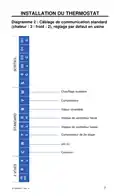
- Page 25: Installation du thermostat Câblage de communication standard Réglage par défaut en usine Chauffage auxiliaire Compresseur Valve réversible Vitesse de ventilateur haute Vitesse de ventilateur basse Compresseur de 2e étage 24V AC
- Page 26: Installation du thermostat Câblage de communication standard Avec une configuration de compresseur à un étage, Y2 peut être utilisé comme signal de sortie d'occupation. Chauffage auxiliaire Compresseur Valve réversible Vitesse de ventilateur haute Vitesse de ventilateur basse 24V AC Commun
- Page 27: Installation du thermostat Diagramme 4 : Câblage de communication standard Avec une configuration de compresseur à un étage, Y2 peut être utilisé comme signal de sortie d'occupation pour contrôler l'alimentation en air d'appoint en fonction de l'occupation. Chauffage auxiliaire Compresseur Vitesse de ventilateur haute Vitesse de ventilateur basse Facultatif : Sortie occupation 24V AC Commun
- Page 28: Installation du thermostat Menu de l’installateur Pour accéder au menu de l’installateur, utilisez le bouton Power pour éteindre le thermostat. Maintenez le bouton Mode enfoncé durant 2 secondes jusqu’à ce que « Setup Mode » apparaisse sur l’écran. + / – : Permet de modifier la sélection des paramètres. Mode : Permet d'accéder à l'élément de menu suivant. Fan : Permet de revenir à l'élément de menu précédent. Power : Permet d'enregistrer les modifications et de quitter. Au bout de deux minutes sans pression sur une touche, le menu expire et revient à l'écran noir de mise hors tension.
- Page 29: Installation du thermostat Menu de l'installateur Réglage par défaut menu Disponibilité Description de 8 fils de 2 voies Réglage des heures actuelles (heure militaire) Réglage des minutes actuelles Mode ventilateur Thermopompe Inversion automatique
- Page 30: Installation du thermostat Menu de l'installateur Zone morte (F) Ce décalage est ajouté au différentiel de refroidissement et de chauffage 1 en mode d'inversion automatique. Ce paramètre n'est disponible que si l’inversion automatique est activée. Temp. refroidissement min. (F) Ne peut pas être une température supérieure à la valeur 18. Max Heating Temp (F) Ne peut pas être une température inférieure à la valeur 17. Décalage de température ambiante (F) Il s'agit d'un décalage pour étalonner la lecture de la température ambiante. Économies d'énergie selon l’occupation Les déviations de température sont autorisées lorsque aucune occupation n'est détectée.
- Page 31: Installation du thermostat Menu de l'installateur Temporisateur d'état d'occupation (en minutes) Le nombre de minutes pendant lequel l'état d'occupation est maintenu lorsqu'un événement d'occupation se produit. Remarque : Disponible seulement si le paramètre 21 (économies d’énergie selon l’occupation) est réglé sur Y ou S. Heure de début des économies d'énergie programmées (heure militaire) Sélectionnez l'heure de début à laquelle les déviations dues à l'occupation sont autorisées. Heure d’arrêt des économies d'énergie programmées (heure militaire) Sélectionnez l'heure à laquelle les déviations dues à l'occupation ne sont plus autorisées. Remarque : Disponible seulement si le paramètre 21 (économies d’énergie selon l’occupation) est réglé sur S. Dispositif 1 Utilisé pour contrôler le relais externe câblé à la sortie O1 sur le bornier. Réinitialisation des valeurs par défaut Sélectionnez pour restaurer tous les paramètres de programmation par défaut après avoir quitté le menu d’installateur.
- Page 32: Utilisation du thermostat Aperçu du thermostat Avant d’utiliser le thermostat, vous devriez être familier avec ses fonctions, son affichage et l’emplacement/le fonctionnement des boutons. Boutons et sélecteurs du thermostat Affichage Mise sous/hors tension Point de consigne sélectionné Indicateur de communication à 2 voies Options 2 voies : Basse, Haute (vitesses) Options 8 fils : Basse auto, Haute auto, Basse et Haute Sélection du mode Options 2 voies : Ventilateur en chauffage, refroidissement
- Page 33: Dépannage Aucun affichage Appuyez sur le bouton Power pour vous assurer que le thermostat n'est pas éteint. Assurez-vous que la tension est de 24 VAC; l’afficheur ne fonctionnera pas sans cette tension. Le système de ventilation ne se met pas en marche correctement Vérifiez le bon état du câblage. Aucun bouton du thermostat ne fonctionne Assurez-vous que la tension est de 24 VAC; l’appareil ne fonctionnera pas sans cette tension. Le thermostat s’allume et s’éteint trop fréquemment Ajustez l’écart de température. Le ventilateur ne s’arrête pas Vérifiez la sélection de ventilateur. Le compresseur ne fonctionne pas ou s’éteint immédiatement après une modification de fonction ou de réglage Il y a une temporisation de trois minutes et un temps de fonctionnement minimum de trois minutes pour le compresseur. Le ventilateur ne fonctionne pas ou s'éteint immédiatement lors du changement de fonction ou de réglage Ce phénomène est normal. Réinitialisation du thermostat ou de ses réglages Pour rétablir les paramètres d’usine par défaut uniquement, voir le paramètre 99 dans le menu de l’installateur.
- Page 34: Page 34
- Page 35: Garantie limitée du thermostat Période de la garantie : un (1) an à compter de la date du premier achat. GE Appliances remplacera : remplacement complet du thermostat comportant un défaut de matériaux ou de fabrication. Ce que GE Appliances ne couvre pas : frais de déplacement pour réparation vers votre emplacement. Une installation mal effectuée. Vous êtes responsable d’effectuer correctement les raccords électriques de votre produit. Une défectuosité du produit causée par des modifications au produit ou par son usage déraisonnable. Dans les locaux commerciaux, la main-d’œuvre nécessaire pour déplacer l’appareil après son installation initiale. Le remplacement des fusibles ou l’enclenchement des disjoncteurs du site. Les bris du produit causés par une tension d’alimentation électrique inadéquate, un accident, un incendie, les inondations et les cas de force majeure. Exclusion des garanties implicites : votre seul et unique recours est l’échange du produit comme prévu dans cette garantie limitée. Cette garantie limitée est consentie à son premier acheteur et à tout propriétaire subséquent pour les produits achetés pour utilisation aux États-Unis et au Canada.
- Page 36: Déclaration de la FCC Cet équipement a été testé et déclaré conforme aux limites d’un dispositif numérique de Classe B, conformément à la partie 15 des règles de la FCC. Ces limites sont définies afin d’assurer une protection raisonnable contre le brouillage nuisible dans une installation résidentielle. Cet équipement génère, utilise et émet des fréquences radio qui, en cas d’une installation erronée ou d’une utilisation non-conforme aux instructions de ce manuel d’utilisation, peuvent causer un brouillage nuisible aux communications radio. Il n’y a aucune garantie qu’un brouillage nuisible ne se produira pas dans une installation particulière. Si cet équipement cause un brouillage nuisible sur votre poste radio ou de télévision, il est conseillé à l’utilisateur d’essayer de pallier ce brouillage nuisible en prenant l’une ou l’autre des mesures suivantes. Réorienter ou déplacer l’antenne de réception. Augmenter la distance entre l’équipement et le récepteur. Brancher l’équipement dans une prise d’un circuit qui diffère de celui auquel le récepteur est branché. Consulter le revendeur ou un technicien en radio-télévision pour obtenir de l’aide.