Dettson R02P034 Communicating Thermostat Instruction Manual


INSTALLATION INSTRUCTIONS AND
HOMEOWNER’S MANUAL
Communicating Thermostat
Model : R02P034
Printed in Canada on
100% recycled paper
2022-11-02
X00507 Rev.A

| General | Details |
|---|---|
| Name | Dettson R02P034 Communicating Thermostat Instruction Manual |
| Make | Dettson |
| Language | English |
| Filetype | PDF (Download) |
| File size | 0.28 MB |


Dettson 2-Stage WiFi Thermostat R02P033 Owner’s Manual

Dettson R02P034 Communicating Thermostat Instruction Manual Overview
Summary of Contents
- Page 1: Installation instructions and homeowner’s manual Communicating thermostat Model: R02P034 Printed in Canada on 100% recycled paper
- Page 2: Failure to read and follow all instructions carefully before installing or operating this control and system could cause personal injury and/or property damage. The R02P034 is our most powerful thermostat yet. Control your home comfort system powered by an improved full LED display control unit with touch sensitivity. Adjust the desired temperature with a wide setpoint range of 41°F to 95°F. The unit works well with 24 VAC Climate Talk architecture; powered by gas, electric heat, heat pumps, and central air conditioning based systems. With smart systems such as autoconfigure, autochangeover, and advance diagnostics, you can take a hands-off approach. Additional features include humidity control, dehumidification control, dual fuel control, and filter change-out indicator. This product does not contain mercury, but it may replace a product that contains mercury. Mercury and products containing mercury must not be discarded in household trash. For proper disposal of a product containing mercury, place it in a suitable shipping container.
- Page 3: Installation Wiring requirements Installing thermostat Operation Display and controls System modes Clock setting Schedule setting Alarms Thermostat settings Equipment user menu
- Page 4: Page 4
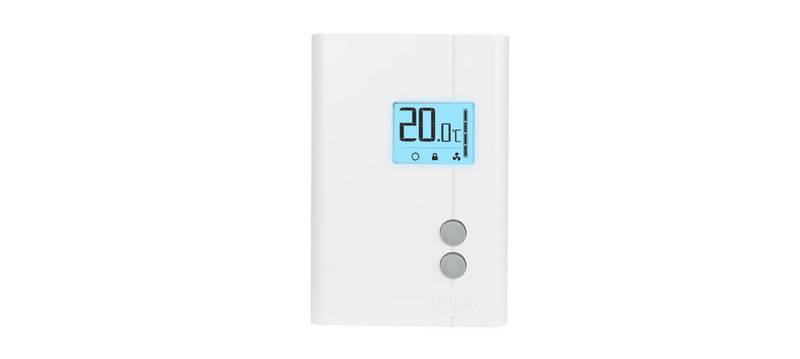
- Page 5: Operation section covers the display and controls of the device. The temperature display shows the current temperature. Thermostat waiting indicates the system is in standby mode. The weekday is displayed for user reference. Temperature scale can be adjusted based on preference. Time display shows the current time or menu item value. Continuous fan mode allows for constant airflow. Adjustment buttons are used for setting temperature and other parameters. Operating mode indicates the current function of the device. The mode select button allows users to switch between different operating modes.
- Page 6: System modes include On/Off, Fan Modes, and Operating Modes. The On/Off button completely turns off the system, stopping all heating, cooling, or ventilation commands. Fan modes can be switched between Fan On and Fan Auto, with the fan running only during heating or cooling demand in Auto mode. Operating modes include Heat, Auxiliary Heat, Cool, and Auto, with the thermostat automatically switching between heating and cooling as needed. To set the time and day, press the appropriate buttons to adjust the blinking value and return to the main display after completion. Scheduling mode is disabled by default, and section 3 provides instructions for setting the desired schedule type. When scheduling is enabled, access clock configuration to display schedule parameters.
- Page 7: Start is displayed indicating the start time of the current period is being set. Use the controls to adjust the blinking parameter. The parameters include period start time (hours), period start time (minutes), operating mode during the period, fan mode, modulation (unused), and set point. The blinking cursor will cycle through these parameters for all periods and for all day groups. Once the schedule is set, to enter this mode press and hold at the main display. The thermostat will display an alarm when an alarm is raised. The alarm code will be shown in the top-left corner. Display Code and Description include air filter cleaning reminder, defective temperature sensor, and communication error. Actions include cleaning or replacing the air filter, replacing the thermostat, and checking equipment and wiring.
- Page 8: Thermostat settings can be accessed using specific buttons. Parameters can be adjusted by changing their values. Users can navigate through parameters and return to the main display. Temperature adjustment allows for minimum and maximum set points. Cooling and heating settings are adjustable within specified ranges. The air filter counter and its reset function are included in the settings. Options for enabling or disabling features like beeper and dimming are available. Scheduling programs can be set for different days and periods. Clock format can be adjusted to 24-hour settings. Display options include humidity or outdoor temperature selection.
- Page 9: Equipment operating information and options can be accessed by long pressing the button. Use the menu item to change the parameter value. Each Equipment User Menu has submenus to divide the information into categories. Each piece of equipment has a different set of submenus, with different parameters. The submenus and the information they provide are represented in the following tables. A X in the following tables indicate alpha or numerical character. For more information on each menu item, refer to the manual of the corresponding equipment. Chinook Gas Furnace User Menus. Used to display equipment information. Display operating info of last 2 weeks.
- Page 10: Status 1 includes parameters such as main limit control status, main reset limit control status, and inducer output status. The system indicates the status of the low and high pressure switches, as well as the gas valve percentage open. Flame sensor status can be categorized as off, marginal, good, or unexpected. Blower CFM is noted, indicating the furnace blower's airflow. Status 2 outlines the operating mode of the system, including mod heat, lo heat, hi heat, and off. Blower motor manufacturer and RPM are specified, along with the maximum CFM the blower provides. The humidifier output relay and electronic air cleaner output relay statuses are also included. The 2-week history section details modulating heat hours and cycles, as well as blower hours and cycles. Life history tracks total days powered, modulating heat hours, and blower hours of operation. Fault history displays up to six faults and indicates how many days ago each fault occurred.
- Page 11: Unit info includes model number, serial number, and software version. Setup parameters involve heat rise adjustments, minimum and maximum heat adjustments, and resetting all defaults. Status section provides current air flow, percentage of active electric elements, and firmware version. Fan settings include continuous fan ratio and temperature rise. Autobackup options detail whether it is enabled, the mode, wait time, update delay, and lockout temperature. System parameters cover AC/HP on/off delay, fan delay, and dual heat options. Reset options allow for restoring factory values. FC values will be shown if a more precise value has been configured at the furnace control.
- Page 12: Interface board user menus (Alizé) Status Compressor frequency Fan speed Coil temperature Outdoor fan speed Indoor coil temperature Compressor discharge temperature Model Version Factory values

Danfoss RT 115 Thermostat Installation Guide

Roth Minishunt Plus Wireless Room Thermostat Installation Guide

Beca BAC-1000 Series WiFi Thermostat User Guide

HIVE 852031 Mini Wireless Heating Smart Thermostat Instructions

Commercial Electric HTSA15CWB Smart Thermostat User Guide

Centrometal TU-DT-2024-ENG Thermostat Instruction Manual
STELPRO STE241 Low Voltage 24V Electronic Thermostat User Guide

Honeywell RCH9310 Lyric Round WiFi Thermostat User Guide

Carrier 53DFS250-SL Programmable Digital Thermostat Owner’s Manual

QUIETWarmth Type UCG Thermostat User Manual