azbil TY6000Z2000 Neostat Room Thermostat Instruction Manual


AB-7258
Specifications/Instructions
Neostat
Room Thermostat, Room Humidistat
General
Neostat Models TY600_Z, TTY6023Z, and TY900_Z are
series of electric room thermostat. Neostat Model HY6000Z
is an electric room humidistat.
Neostat is similar in design and size to Neosensor, the
electronic room temperature and/or humidity sensor.
A temperature-sensitive diaphragm is adopted for the
thermostat, and a moisture-sensitive nylon ribbon is adopted
for the humidistat.
Features
●
Simple connection to an actuator allows easy
temperature/humidity control.
●
●
Compact (thin) and lightweight.
Several installation types selectable in combination with
optional auxiliary devices.
Model Numbers
Thermostat
Switch for heating/cooling
changeover
Our corporate logo
(on the cover)
Model number
Control action
Range
TY6000Z2000
TY6000Z2000-1
TY6001Z2000
TY6001Z2000-1
TTY6023Z2000
TTY6023Z2000-1
TY9000Z2000
TY9000Z2000-1
TY9001Z2000
TY9001Z2000-1
Note:
Two-position, one-step
10 °C to 30 °C
Without switch
Printed
Not printed
Printed
Not printed
Printed
Not printed
Printed
Not printed
Printed
Not printed
With switch
Two-position, two-step
Proportional*
Without switch
Without switch
With switch
*
Use Neostat (proportional type) with our Control Motor, ACTIVAL™, etc.
Humidistat
Model number
Control action
Tow-position
Range
Our corporate logo (on the cover)
HY6000Z2000
30 %RH to 90 %RH
Printed
HY6000Z2000-1
Not printed
© 2014-2018 Azbil Corporation All Rights Reserved.
1

| General | Details |
|---|---|
| Name | azbil TY6000Z2000 Neostat Room Thermostat Instruction Manual |
| Make | azbil |
| Language | English |
| Filetype | PDF (Download) |
| File size | 0.75 MB |


azbil TY6000Z2000 Neostat Room Thermostat Instruction Manual Overview
Summary of Contents
- Page 1: Specifications/Instructions Neostat models TY600_Z, TTY6023Z, and TY900_Z are a series of electric room thermostats. Neostat Model HY6000Z is an electric room humidistat. Neostat is similar in design and size to Neosensor, the electronic room temperature and/or humidity sensor. A temperature-sensitive diaphragm is adopted for the thermostat, and a moisture-sensitive nylon ribbon is adopted for the humidistat. Simple connection to an actuator allows easy temperature/humidity control. Compact (thin) and lightweight. Several installation types selectable in combination with optional auxiliary devices. Two-position, one-step control action for thermostats ranges from 10 °C to 30 °C. Use Neostat (proportional type) with our Control Motor, ACTIVAL™, etc. Humidistat model HY6000Z2000 has a control action range of 30 %RH to 90 %RH.
- Page 2: Safety instructions emphasize the importance of reading the manual carefully and using the product as specified. The product is designed for general air conditioning use and should not be used in situations where human life may be at risk or in radiation-controlled areas without consulting Azbil Corporation. For applications requiring safety, fail-safe design and regular maintenance should be considered. The recommended design life of the product is 11 years, during which it can operate reliably with the lowest failure ratio. Warnings and cautions alert users to the potential for serious injury or material loss due to improper handling. Specific symbols indicate various safety messages, such as warnings of electric shock, prohibited actions, and obligatory actions to prevent danger. Azbil Corporation disclaims responsibility for any results from the customer's use of the product. Users are advised to keep the manual nearby for quick reference. The product's failure ratio may increase if used beyond its recommended design life. For system design or product applications, users should contact Azbil Corporation.
- Page 3: Caution: Use the product under the operating conditions as listed in the specifications. Failure to do so might cause fire or device failure. Use the product within the rated operating ranges as listed in the specifications. Failure to do so might cause device failure. Installation and wiring must be performed by qualified personnel in accordance with all applicable safety standards. All wiring must comply with applicable codes and ordinances. Before wiring, be sure to turn off the power to the product. Failure to do so might cause electric shock. To connect the wires to the screw terminals, use crimp terminal lugs with insulation. Failure to do so might cause fire or device failure due to short circuit. Do not disassemble the product. Doing so might cause electric shock or device failure.
- Page 4: Part numbers of optional items Mount Neostat with the following optional items (sold separately). Order necessary items. Specifications Differential: 1.5 ± 1 °C (in 10–30 °C range) Temperature difference Model TTY6023Z 2 ± 1 °C fixed (in 10–30 °C range) between steps. Sensing elements Temperature-sensitive diaphragm Moisture-sensitive nylon ribbon Environment conditions Rated operating conditions: Ambient temperature 0–50 °C, Ambient humidity 10–90 % RH (without condensation). Contact rating of two-position control Model TY600_Z: 125 V AC, 6 A; 250 V AC, 3 A; 24 V DC, 1 A. Color Pale gray (BN-85, Japan Paint Manufacturers Association in 2003). Installation Connection with the mounting kit (sold separately). Notes Minimum allowable current is 50 mA. Select a device (load) of which the Neostat contact rating is tolerable.
- Page 5: Dimensions of Neostat are provided. Secure more than 15 mm clearance inside the mounting wall when installing Neostat. Dimensions for the adapter are also included.
- Page 6: Installation Use the product under the operating conditions as listed in the specifications. Installation and wiring must be performed by qualified personnel in accordance with all applicable safety standards. The installation location of Neostat largely affects temperature or humidity control. Do not tighten or loosen the screws except those described in the installation steps. Hold the guide, but not the setting dial, when lifting the Neostat main unit. Install Neostat on an indoor wall where representative temperature/humidity can be measured. Do not install Neostat on a wall where heat stays on or air circulation is interfered. Humidity/temperature sensing is affected by draft, downdraft, and hot/cold air from water pipes/ducts. Chemicals or oils should be wiped immediately with a dry soft cloth to prevent chemical cracks. Do not install Neostat outdoors or in a duct.
- Page 7: Precautions for installation Secure the clearance for wiring inside the wall. Install Neostat with a dedicated mounting kit suitable for your application. Do not allow any refuse such as an electric wire scrap to get inside Neostat. Do not allow the lead wires caught between the mounting surface of Neostat and the wall. Do not put heavy load on the setting dial or lead wires. If air infiltrates to the rear side of the Neostat, seal the outlet box. Be sure to tighten all the screws necessary for installation. Tighten the screws with the specified torque to avoid damage. Be careful not to touch the diaphragm or nylon ribbon when Neostat is uncovered. After installation, leave Neostat to adapt to ambient conditions.
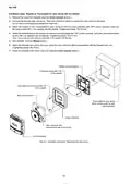
- Page 8: Installation steps: Neostat directly on a wall (for new installation) Mount the outlet box cover so that the two mounting holes are vertically aligned. Remove the cover from Neostat. Unscrew the Neostat main unit screw and lift the guide to remove the main unit from the base. Attach the Neostat base to the outlet box cover with the arrow pointing upwards, using two pan-head machine screws. Wire Neostat. Attach the Neostat main unit to the base using the main unit screw. Attach the Neostat cover to the main unit.
- Page 9: Installation steps: Neostat directly on a wall with the adapter (for replacement of the former model) Remove the cover from Neostat. Unscrew the Neostat main unit screw and lift the guide to remove the main unit from the base. Attach the adapter to the outlet box cover with the arrow pointing upwards. Attach the Neostat base to the adapter with the arrow pointing upwards. Wire Neostat. Attach the Neostat main unit to the base using the main unit screw. Attach the Neostat cover to the main unit.
- Page 10: Installation steps: Neostat on Thermoplate for open wiring with the adapter Remove the cover from Neostat. Unscrew the Neostat main unit screw and lift the guide to remove the main unit from the base. Attach the adapter to the Thermoplate for open wiring with the arrow pointing upwards. Attach the Neostat base to the adapter with the arrow pointing upwards. Do not use pan-head machine screw (M4 x 10) supplied with Neostat. Wire Neostat. Attach the Neostat main unit to the base using the main unit screw (M3). Attach the Neostat cover to the main unit.
- Page 11: Installation steps: Neostat on Thermoplate with the adapter Attach the mounting plate of Thermoplate to the outlet box cover with two pan-head machine screws supplied with Thermoplate. Attach the main unit of Thermoplate to its mounting plate with two pan-head machine screws supplied with Thermoplate. Attach the adapter to Thermplate so that the arrow points upwards, using two flat-head tapping screws supplied with Thermoplate. Remove the cover from Neostat. Unscrew the Neostat main unit screw and hold and lift the guide to remove the main unit from the base. Attach the Neostat base to the adapter so that the arrow points upwards, using two pan-head machine screws supplied with the adapter. Wire Neostat. Attach the Neostat main unit to the base using the main unit screw preassembled with the Neostat main unit. Attach the Neostat cover to the main unit.
- Page 12: Installation steps: Neostat in Multi-Thermocase with the adapter Mount Neostat onto one of the mounting windows with 66.7 mm mounting dimension of the device mounting plate. Attach the adapter to the device mounting plate of Multi-Thermocase using two pan-head machine screws (M3 x 6). Remove the cover from Neostat. Unscrew the Neostat main unit screw and lift the guide to remove the main unit from the base. Attach the Neostat base to the adapter so that the arrow points upwards, using two pan-head machine screws (M4 x 6). Wire Neostat. Attach the Neostat main unit to the base using the main unit screw (M3). Attach the cover of Multi-Thermocase. In Multi-Thermocase, Neostat is installed with its cover removed.
- Page 13: Wiring Installation and wiring must be performed by qualified personnel in accordance with all applicable safety standards. All wiring must comply with applicable codes and ordinances. Before wiring, be sure to turn off the power to the product. To connect the wires to the screw terminals, use crimp terminal lugs with insulation. Model TTY6023Z2000 adopts lead wire connection and the rest of the models adopt terminal connection. Use M4 crimp terminals to connect wires to the Neostat screw terminals. For connecting wires from the load, use 1.25 mm² or greater stranded annealed copper wires with insulation. For splicing lead wires, use crimp sleeves with insulation. Make sure that all the wires are tightly connected. Wiring diagrams are provided for various models.
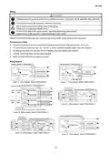
- Page 14: Wiring to the load Select a device (load) of which the Neostat contact rating is tolerable. If a load larger than the Neostat contact rating is connected to Neostat, the contact may be welded and may not turn on or off. Model TY600_Z is the two-position one-step type thermostat for ON/OFF control of an electric motor, electric heater, solenoid valve, auxiliary relay, or the like. Model TTY6023Z is the two-position two-step type thermostat for dual-step ON/OFF control of a packaged air conditioner, electric motor, electric heater, or the like. Model TY900_Z is the proportional type thermostat for proportional control of the Control Motor or ACTIVAL that actuates valve or damper. Modutrol Motor cannot be connected to Neostat. To connect Model TY900_Z to a device other than the above mentioned, ask our salesperson to check if Model TY900_Z is connectable to the device. Model HY6000Z is the two-position one-step type humidistat for ON/OFF control of a solenoid valve, auxiliary relay, or the like. Switching action of two-position control thermostat Model TY600_Z2000(-1) includes contact between terminals L and C, and terminals H and C. Differential for Model TY6001Z2000(-1) is approximately 1.5 °C (fixed).
- Page 15: Thermostat (two-position one-step type) Model TTY6023Z2000 Contact between gray and red wires, white and pink wires, black and pink wires. Cooling (step 1) and (step 2) settings. Heating (step 1) and (step 2) settings. Differential approximately 1.5 °C (fixed). Humidistat (two-position one-step type) Model HY6000Z2000(-1). Contact between terminals H and C, and terminals L and C. Humidifying and dehumidifying settings. Differential approximately 5 %RH (fixed). Setpoint for humidity low and high.
- Page 16: Setting Thermostat model Heating/cooling changeover Remove the cover of Neostat. Set the switch for heating/cooling changeover. Do not change the switch while Neostat and connected equipment are in operation. Adjust the high and low limits of the setting range using the range adjusters. Press lightly to release lock and shift the range adjusters for high and low limits. Lock the setpoint using the range adjusters. Shift the setting dial so that the pointer points to the desired position. Attach the cover to the main unit.
- Page 17: Humidistat model Setpoint is factory-set and locked at 90 %RH. Lock of the setting involves removing the cover, loosening the setting screw, adjusting the setting dial, and reattaching the cover. If the product is installed in an animal breeding facility or an operating room, attach the protection cover when fumigating. Check that fumigants are dried out before removing the cover to avoid chemical cracks. Remove the cover slowly and straightly to prevent damage to the latch. Dispose of the product as industrial waste in accordance with local regulations. Do not reuse all or part of this product.
- Page 18: Page 18

MI-HEAT WT8 WiFi Smart Thermostat User Manual

BEOK CONTROLS BOT-R6W Boiler Thermostat User Guide

INKBIRD ITC-306A Digital Thermostat User Manual

MI-HEAT MTS200 WiFi Thermostat Instruction Manual

neptronic TFC54F3X1 Fan Coil Thermostat Installation Guide

HYSEN HY608 Wi-Fi Digital Heating Thermostat User Manual

Danfoss ECtemp 531 Electronic Thermostat Installation Guide

BEOK TGP53 Wifi Thermostat User Guide
Total Home TTHWD Wired Digital Room Thermostat User Guide

Sygonix 2735095 Wireless Indoor Thermostat Instruction Manual