VEVOR ET-72G Programmable Thermostat Instruction Manual


PROGRAMMABLE THERMOSTATS
MODEL: ET-72G(W)

| General | Details |
|---|---|
| Name | VEVOR ET-72G Programmable Thermostat Instruction Manual |
| Make | VEVOR |
| Language | English |
| Filetype | PDF (Download) |
| File size | 0.19 MB |


VEVOR ET-72G Programmable Thermostat Instruction Manual Overview
Summary of Contents
- Page 1: Programmable thermostats Model: ET-72G(W)
- Page 2: Model: ET-72G(W) This is the original instruction, please read all manual instructions carefully before operating. VEVOR reserves a clear interpretation of our user manual. The appearance of the product shall be subject to the product you received. Please forgive us that we won't inform you again if there are any technology or software updates on our product.
- Page 3: Warning to reduce the risk of injury, user must read instructions manual carefully. FCC information: changes or modifications not expressly approved could void the user's authority to operate the equipment. This device complies with Part 15 of the FCC Rules. Operation is subject to two conditions: this product may cause harmful interference and must accept any interference received. Changes or modifications to this product not expressly approved could void the user's authority to operate the product. This product has been tested and found to comply with the limits for a Class B digital device. These limits are designed to provide reasonable protection against harmful interference in a residential installation. This product generates, uses, and can radiate radio frequency energy. If not installed and used in accordance with the instructions, it may cause harmful interference to radio communications. If this product does cause harmful interference, the user is encouraged to try to correct the interference by various measures.
- Page 4: Consult the dealer or an experienced radio/TV technician for assistance. This product is subject to the provision of European Directive 2012/19/EC. The symbol showing a wheelie bin crossed through indicates that the product requires separate refuse collection in the European Union. The ET-72G series thermostats control the floor heating system based on built-in weekly program. The weekly program runs in 4 or 2 stages per day, 7 days a week. The default weekly program parameters can satisfy most usage scenarios. It is recommended to set the temperature down to save energy when there is no one in the house. The thermostat has built-in adaptive function to adjust heating in advance of the next stage. After turning adaptive on, the thermostat takes a few days to learn the time required. Symbols include On/Off/GFCI reset button, GFCI test button, mode, temperature, sensor selection, and WiFi indicator.
- Page 5: Ground Fault Circuit Interrupter (GFCI) This thermostat has a built-in GFCI function that protects people from electric shock. It is very important to check whether the GFCI function is normal or not every month. Confirm that the thermostat is turned on. Press the [Test Monthly] button. If a red light appears in the upper left corner of the thermostat and GROUND FAULT appears on the screen, the GFCI function is normal. If there is no response, it means the function is invalid, please contact the dealer or electrical installer. Do not press and hold the [Test Monthly] button. Press the [Reset] button. The red light is off and the screen shows the power off state. Press the [Reset] button again. The thermostat is turned on. If in daily use, the red light is on and the screen appears GROUND FAULT.
- Page 6: Reset button indicates the shutdown status and potential ground fault. The GFCI Reset button also functions as the on/off switch. Temporary override temperature is enabled in automatic intelligent mode. Users can modify the set temperature using the ▲ or ▼ buttons. The thermostat has three operating modes: automatic, manual, and frost protection. Automatic mode adjusts the set temperature according to a weekly program. Manual mode allows continuous operation at the set temperature. Frost protection mode maintains a lower temperature range from 41°F to 59°F. To set the mode, access the first level menu by tapping OK. Confirm mode selection by tapping OK after changing the mode with ▲ or ▼.
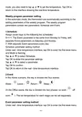
- Page 7: Weekly program parameter setting In the automatic mode, the thermostat runs automatically according to the setting parameters of the weekly program. The weekly program parameters contain two parameters: Schedule and Event. Schedule assigns seven days to the following two schedules: 5+1+1 and 7. Schedule parameter setting method includes tapping OK to enter the first level menu and selecting Schedule. Event divides the day into four events: Wake, Leave, Return, and Sleep. In the Office scene, the day is divided into two phases: on work and off work. The set temperature for each stage can be set separately. Event parameter setting method involves tapping OK to enter the first level menu.
- Page 8: Tap ▲ or ▼ to select Event. Tap OK to enter the week selection. Tap ▲ or ▼ to select the day you want to modify the parameters. Tap OK to enter the stage selection for the day. Tap ▲ or ▼ to select the stage that you want to modify the parameters. Tap OK to enter the temperature setting of the current phase. Tap ▲ or ▼ to select the temperature value you want to set. Tap OK to enter the hour setting for the start time of the current phase. Tap ▲ or ▼ to select the hour of the start time. Note: Parameters no.3 to 9 can only be modified by a certified electrician.
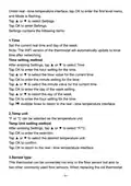
- Page 9: Under real-time temperature interface, tap OK to enter the first level menu. Mode is flashing. Tap ▲ or ▼ to select Settings. Settings contains the following items: Time: Set the current real time and day of the week. The WiFi version of the thermostat will automatically update to local time after networking. Temp unit: °F or °C can be selected as the temperature unit. Sensor type: This thermostat can be connected not only to the floor sensor but also to two other commonly used floor sensors.
- Page 10: There is no need to replace the floor sensor for easy installation. Sensor Type setting method involves entering Settings and selecting Sensor Type. Three sensor applications are available: Room, Floor, and Room.Limit. Room controls room temperature based solely on built-in sensors. Floor controls the floor temperature based solely on the floor sensor. Room.Limit controls room temperature while monitoring the floor temperature not to exceed the upper limit. Sensor Selection setting method involves entering Settings and selecting Sensor Selection. If Room.Limit is selected, you need to set the maximum temperature that the floor can accept. This thermostat has built-in probe and floor sensor calibration function.
- Page 11: Calibration setting method allows adjustment of real-time temperature to match the displayed value of the calibration instrument. The thermostat is suitable for use in both homes and offices, with built-in weekly program parameters for office use. Location setting method enables selection between Office or Home. The thermostat features an adaptive function that preemptively adjusts heating to reach the set temperature. Adaptive setting method allows users to enable or disable the adaptive function.
- Page 12: Troubleshooting E1: Built-in probe failure, please contact your dealer or professional technician. E2: External probe failure, please contact your dealer or professional technician. Installation Loosen the bottom screw by a Phillips screwdriver. Then open the thermostat from the upper right side as shown. Screw the nut out of the groove and do not need to unscrew it. Wire as shown: L/N lead: Connect the power cord using the terminal block. L1/N1 lead: Use a terminal block to connect the load line. IN/SNR terminal: Connect the floor sensor. OUT terminal: Connect to IN/SNR of Power Module. Disconnect the main power supply before wiring. If an electric floor heating cable or mat system requires more than 15 Amps, install a power module. Wiring diameter: 12 to 22 AWG.
- Page 13: Install the back cover into the terminal box and secure it with the set screw. Fit the left side of the front and rear covers as shown. Press the upper half of the right border until you hear a click. Use a screwdriver to secure the bottom screw. Turn on the power and test the GFCI function. To avoid risk of electric shock, disconnect all power coming to the heater at the main service panel before installation of the thermostat. Keep air vents of the thermostat clean and free from obstructions. All wiring must conform to local and national electrical codes and ordinances. Installation must be carried out by qualified personnel. The thermostat is a Class II device (reinforced insulation) used for controlling electrical floor heating.
- Page 14: Connect the power cord using the terminal block. Use a terminal block to connect the load line (Max 15A). Electric floor heating cable/mat must be in accordance with the supply voltage. The terminals are designed to handle a cross-section of wire measuring 12-22 AWG. Supply voltage: 120/240 VAC 50/60 Hz. GFCI: Class A (5 mA trip level). Temperature range: +5 to +45°C / +41 to +113°F. Load: max. 15 A (resistive load). Set point range: +5 to +40°C / +41 to +104°F. Manufacturer: Wuhu Jiahong New Material Co., Ltd.

LATICRETE Strata Heat WiFi Thermostat Instruction Manual

GENERAL LIFE SENNA 300 Wired Room Thermostat User Manual

LUX TX9600TSA Smart Temp Universal 7 Day Programmable Touchscreen Thermostat Instruction Manual

SIEMENS RDH100RF/SET Wireless Room Thermostat with LCD User Guide

technolysis HYT002-WIFI WI-FI Digital Heating Thermostat User Manual

SALUS DT500 Thermostat User Guide

ARUNA 302S RF Digital Room Thermostat User Manual

VIVE TP-S-855C Digital Programmable Thermostat Instruction Manual

Honeywell CT1501 Electromechanical Fuel Saver Thermostat Instruction Manual

NT NetX X-Series Thermostat Installation Guide