
NT NetX X-Series Thermostat Installation Guide


Be sure to avoid the following locations:
BEFORE YOU START
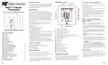
THERMOSTAT CALLOUT
● Behind doors or in corners where freely circulating air is
unavailable
Please read entire install manual. The thermostat will need to
be correctly wired and configured for proper operation. Basic
HVAC configuration can be performed from the thermostat
touchscreen and advanced settings are accessed via your
network and/or the Internet.
● Where direct sunlight or radiant heat from appliances might
affect control operation
● On an outside wall
● Adjacent to, or in line with, conditioned air discharge grilles,
stairwells or outside doors
NetX™ X-Series
Thermostat
INTRODUCTION
● Where its operation may be affected by steam or water
pipes or warm air stacks in an adjacent partition, or by any
unheated / uncooled area behind the thermostat
● Where operation may be affected by lighting dimmers
● Where operation will be affected by the supply air of an
adjacent unit
The X-Series thermostat is a network connected color
touchscreen thermostat with an advanced remote sensor bus,
designed for new or replacement commercial or residential
applications. It supports up to 3 Heat / 2 Cool heat pumps and
2 Heat / 2 Cool conventional systems. Internal webpages help
deliver a near-effortless setup of your daily schedules (4 events
per day), and up to 40 Special and 40 Calendar Events. The
unique scheduling structure also supports the powerful
features of adjustable temporary override times, temperature
ranges, occupied and unoccupied events, keypad lockout, and
many more features.
INSTALLATION AND PROGRAMMING MANUAL
● Near electrical source interference such as arcing relay
contacts
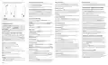
MOUNT THERMOSTAT BACKPLATE
BEFORE YOU BEGIN: Turn off the power to the HVAC
equipment.
Available in both Wi-Fi and Ethernet models, the X-Series
supports NetX CloudConnect™, DirectConnect™, and
PCConnect™ Software Tools.
TIP: If you are replacing an existing thermostat, take a
B
picture of the thermostat wiring for reference.
1. From the factory, the thermostat faceplate is not firmly
connected to the backplate. While holding the thermostat,
firmly near the bottom, gently pull apart the backplate from
the faceplate.
Core Features
● 4 independent schedules per day
● 40 Calendar Event Schedules
1
2
3
4
5
6
7
8
9
Special Status Notifications
● 40 Special Event Schedules
2. Place the rectangular opening in the backplate over the
equipment control wires protruding from the wall. Use the
backplate as a template and mark the location of the two
mounting holes.
Secondary Notification Icons
WWW.NETWORKTHERMOSTAT.COM
TABLE OF CONTENTS
● Integrated Humidity Sensor
Current Equipment Mode Indicators
Lock, Override and Hold Icons
Current Operation Status Icons
Secondary Status Icons
Remote Sensor Value (humidity and temperature)
Remote Sensor Icons (temperature, indoor, outdoor icons)
Occupancy Detection Icon
● Integrated Weather with Current Conditions & 7-Day Forecasts
● Occupancy Sensor Input
● 14 Remote Sensors: up to 6 indoor, 1 humidity, 1 outdoor,
and up to 3 auxiliary sensors for monitoring items such as
supply air, return air, walk-in refrigerators and freezers, etc.
● 2 Digital Inputs for Fault Conditions, including Condensate
and Equipment Faults
NOTE: There are several versions of the X-Series
A
thermostat. The wiring instructions for the equipment are
Before You Start
1
1
1
1
1
1
1
2
2
2
2
2
3
3
3
3
3
4
4
4
4
identical.
Introduction
3. Use the supplied anchors and screws for mounting on
drywall or plaster; drill two 3/16” (5mm) diameter holes at
the marked locations; tap the nylon anchors in flush to the
wall surface and fasten backplate using the supplied screws.
What is in the box?
● Email & Text Message Alerting for 4 Recipients
● Alerts include Hi/Lo Temps for Indoor, Outdoor, Supply,
Return, and Aux Temps, Inefficient Equipment Runs, Change
Filter Notifications, and Two Digital Inputs: 19 Alerts in All
10 Dot Matrix Display
11 Clock Display
Copyright Notice
Thermostat Callout
12 Menu Button
Thermostat Location
WARNING: Do not over tighten the screws!
13 Mode Button
C
Mount Thermostat Backplate
Thermostat Setup
14 Fan Button
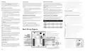
4. Connect the wires from your system to the thermostat
terminals as shown in the Wiring Diagrams section of this
manual. Carefully dress the wires so that any excess is
pushed back into the wall cavity or junction box. Ensure that
the wires are flush to the plastic backplate. The access hole
should be sealed or stuffed to prevent drafts from affecting
the thermostat.
WHAT IS IN THE BOX?
15 Vacation Button
● (1) X-Series Thermostat Faceplate
● (1) WBM-WiFi or WBM-IP Communication Backplate
● (2) 3/16 Drywall anchors
● (2) Mounting Screws
● (1) Installation Manual
16 Resume/Cancel/Power Button
17 Day of Week Icons
18 Active Schedule Icons
19 Current Temperature Display
20 Up Button (Up Arrow)
21 Down Button (Down Arrow)
22 Back Button (Left Arrow)
23 Accept Button (Right Arrow)
Touchscreen User Menu Settings
Touchscreen Installer Menu Settings
Touchscreen Temperature Override
Additional Settings and Features
Remote Sensors (optional)
Programming The Thermostat
Wiring Diagrams
Reattach Faceplate
COPYRIGHT NOTICE
This manual and its content is a copyright of Network
Thermostat - © Network Thermostat 2020. All rights reserved.
5. Reattach faceplate to backplate by placing the top of the
faceplate over the top lip of the backplate.
6. Gently swing the thermostat down and press on the bottom
center edge until it snaps in place. This is a tight connection,
but may require a little wiggle to align the pins on the
faceplate with the screw terminals on the backplate before it
snaps into place.
Terminal Connection Callouts
Independent Power Source (Optional)
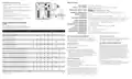
Wiring Diagram Cross Reference Chart
Specifications
THERMOSTAT LOCATION
Any redistribution or reproduction of part or all of the contents
in any form is prohibited other than the following:
To ensure proper operation, the thermostat should be mounted
on an inside wall in a frequently occupied area of the space. In
addition, its position must be at least 18” (46 cm) from any
outside wall, and approximately 5’ (1.5 m) above the floor in a
location with freely circulating air of an average temperature.
1. You may print or download for your use only
2. You may not, except with our express written permission,
distribute or commercially exploit the content, nor may you
transmit it or store it in any other website or other form of
electronic retrieval system.
FIVE (5) Year Limited Warranty
FCC Regulatory Information
240273-03


| General | Details |
|---|---|
| Name | NT NetX X-Series Thermostat Installation Guide |
| Make | NT |
| Language | English |
| Filetype | PDF (Download) |
| File size | 0.3 MB |
 (1 votes, average: 5.00 out of 5)
 Loading...

NT NetX X5N-NX Thermostat Instruction Manual

NT NetX X5 IP Ethernet Thermostat Instruction Manual

NT NetX X5N-SM Thermostat Installation Guide

NT NetX X-Series Manual: Questions and Answers
How do I mount the NT NetX X-Series thermostat backplate?
Position the rectangular opening over wall wires, mark mounting holes, drill and anchor, then fasten with supplied screws.
- Hold the thermostat firmly near the bottom and gently pull the backplate from the faceplate.
- Place the rectangular opening in the backplate over control wires protruding from the wall.
- Mark the location of the two mounting holes using the backplate as a template.
- Drill two 3/16" (5mm) diameter holes at marked locations.
- Tap the nylon anchors flush to the wall surface.
- Fasten the backplate using the supplied screws; do not over tighten. Installation Guide, p. 1
What do the icons on the NT NetX X-Series display mean?
| Icon | Meaning |
|---|---|
| Current Equipment Mode Indicators | Which heating or cooling stage is active |
| Lock, Override and Hold Icons | Status of keypad lock and temporary overrides |
| Current Operation Status Icons | What the thermostat is currently doing |
| Occupancy Detection Icon | Whether occupancy sensor detects presence |
| Remote Sensor Icons | Temperature readings from remote sensors |
| Active Schedule Icons | Which schedule is currently running |
More NT thermostat manuals

finder 1C.B1 Bliss2 Smart Thermostat User Manual

Drayton 2290M Mains Digital Room Thermostat User Manual

WATTS BT-A03 RF Electronic Room Thermostat Installation Guide

Thermafloor HT1 Thermostat White App Electric Mat Thermostat User Guide

NIBE RMU S40 Room Thermostat Instruction Manual

GENERAL Life MITRA 250S RF Wireless Room Thermostat User Guide

DEVIreg 316 Electronic Thermostat Installation Guide

Google G953-01573-01-A Nest 4th Gen Smart Wi-Fi Thermostat Owner’s Manual

Amana MMW-2 Horizontal Digital Wireless non EMS Wall Thermostat Instruction Manual

PECO TW180 Thermostat Instruction Manual