TRANE XR202 Programmable Thermostat User Guide


Trane XR202
Programmable Thermostat
TCONT202AS11MA
Installation and User Guide
ALL phases of this installation must comply with NATIONAL, STATE AND LOCAL CODES
IMPORTANT — This Document is customer property and is to remain with this unit.
These instructions do not cover all variations in systems or provide for every possible contingency to be met in connection with
the installation. Should further information be desired or should particular problems arise which are not covered sufficiently
for the purchaser’s purposes, the matter should be referred to your installing dealer or local distributor.
Pub No. 18-HD51D1-1C-EN
Part No. 37-7769005
September 2020

| General | Details |
|---|---|
| Name | TRANE XR202 Programmable Thermostat User Guide |
| Make | Trane |
| Language | English |
| Filetype | PDF (Download) |
| File size | 0.33 MB |


TRANE BAYECON089A Programmable Touch Screen Thermostat Instruction Manual

TRANE XR103 Non-Programmable Heat Pump Thermostat User Guide

TRANE XR102 Non-Programmable Thermostat User Guide

TRANE SC360 Link System Controller and Smart Thermostat Instructions

TRANE XR202 Programmable Thermostat User Guide Overview
Summary of Contents
- Page 1: Trane XR202 programmable thermostat installation and user guide. All phases of this installation must comply with national, state, and local codes. This document is customer property and is to remain with this unit. These instructions do not cover all variations in systems or provide for every possible contingency. For further information or particular problems not sufficiently covered, refer to your installing dealer or local distributor. Pub No. 18-HD51D1-1C-EN. Part No. 37-7769005. September 2020.
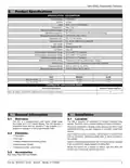
- Page 2: Installation and user guide Safety To prevent electrical shock and/or equipment damage, disconnect electric power to the system at the main fuse or circuit breaker box until installation is complete. To prevent compressor and/or property damage, if the outdoor temperature is below 55°F, do not operate the cooling system. Failure to read and follow all instructions carefully before installing or operating this control could cause personal injury and/or property damage. This information is intended for use by individuals possessing adequate backgrounds of electrical, mechanical, HVAC, and experience. Attention: Mercury notice. This product does not contain mercury, but may replace a product that does. Live electrical components! During installation, testing, servicing, and troubleshooting, it may be necessary to work with live electrical components. Do not use on circuits exceeding specified voltage. Higher voltage will damage control and could cause shock or fire hazard. Do not short out terminals on gas valve or primary control to test. Short or incorrect wiring will burn out the thermostat and could cause personal injury and/or property damage.
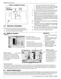
- Page 3: Programmable thermostat XR202 is designed for installation in climate-controlled living spaces. The unit should be placed in a central location with good circulation. It features a scheduling mode that can operate a 7-day program, 5-1-1 program, or operate in a non-programmable mode. For proper temperature sensing, avoid exposing the thermostat to heat radiated from lamps, sunlight, fireplaces, or any other radiant heat source. Avoid locations close to windows, behind doors, or alcoves with poor air circulation. The thermostat comes with a sub-base, mounting screws, nylon drywall anchors, and an installation/user guide. Select a location that prevents the thermostat from being directly exposed to air currents from supply registers or ceiling fans. Mount the control on a section of interior wall that does not contain hot or cold water pipes or ductwork. The thermostat supports heating, cooling, and off system modes. It operates with a temperature display range from 32°F to 99°F.
- Page 4: Installation and user guide Record color and terminal marking of each wire. Disconnect the wires from the existing thermostat being careful not to allow them to fall back into the wall. Remove the existing thermostat from the wall. Pull the thermostat body off the thermostat base. Forcing or prying on the thermostat will cause damage to the unit. Connect wires to terminal block on base using appropriate wiring diagram. Push excess wire into wall and plug hole with a fire resistant material to prevent drafts from affecting thermostat operation. Do not exceed the specification ratings. All wiring must conform to local and national electrical codes and ordinances. Premium AA alkaline batteries are required when C-wire is not available. To replace batteries, set system to OFF, remove thermostat from wall and install the batteries in the rear along the top of the thermostat.
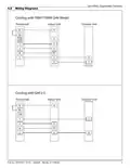
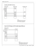
- Page 5: Programmable thermostat Wiring diagrams Cooling with TAM7/TAM9 (24V mode) Wire third party condensate overflow switches between Y of the thermostat and Y1 of the airflow control board. X2 is required to energize aux heat during defrost. Cooling with GAF2-S thermostat Wire third party condensate overflow switches between Y of the thermostat and Y1 of the airflow control board. X2 is required to energize aux heat during defrost.
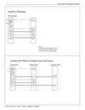
- Page 6: Installation and user guide Cooling with S9V2 furnace Thermostat Indoor unit Outdoor unit Wire third party condensate overflow switches between Y of the thermostat and Y1 of the airflow control board. X2 is required to energize aux heat during defrost. Heat cool package with variable speed blower.
- Page 7: Trane XR202 programmable thermostat Heat/cool package Thermostat wiring details Notes on wiring third party condensate overflow switches X2 requirement for energizing auxiliary heat during defrost Cooling with TEM6 or variable speed gas furnace Indoor and outdoor unit connections Wiring color codes for thermostat connections Publication number and date Part number
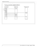
- Page 8: Installation and user guide Cooling with GAT2, GAM2 & TEM3, 4 Thermostat Indoor unit Outdoor unit Wire third party condensate overflow
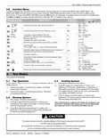
- Page 9: Programmable thermostat Installer menu To prevent changes that may affect system performance, this thermostat has an installer menu and a user menu. The installer menu provides access to every option, while the user menu provides access to items that will not affect system performance. To access the installer menu press the menu button for 8 seconds. Heat cycle rate determines how often the heat will turn on. Cool cycle rate determines how often the cooling will turn on. Compressor lockout protects the compressor from short cycling. Maximum heat limit is the maximum set point for heat mode. Minimum cool limit is the minimum set point for cool mode. Early start allows heating or cooling to begin early to reach the programmed temperature on time. Keypad lock prevents unwanted changes to the thermostat.
- Page 10: Installation and user guide Thermostat overview Before you begin using your thermostat, you should be familiar with its features, display and the location/operation of the thermostat buttons and switches. Thermostat buttons and switches Fan switch System switch Backlight button (located on the top of the thermostat) Battery status indicator Low battery indicator Permanent hold (bypassing the schedule) Temperature setpoint Appears when the keypad is locked (to prevent unwanted changes) Access the schedule and customize thermostat features
- Page 11: Programmable thermostat To customize thermostat settings, press the Menu button from the home screen. Use the or buttons to highlight Settings and press Next. The default program is 5-1-1 Day, but can be setup as a 7-Day or Non-Programmable thermostat. Hold temperature (bypassing the schedule) – With the System switch set to Heat or Cool, momentarily press the Hold button. Program override (temporary hold) – The thermostat will override the schedule until the next programmed time period. Keypad lockout – To prevent unwanted changes, the buttons can be disabled. This thermostat is programmed with energy saving settings for all days of the week. The heating schedule can be modified through the Menu. Press Exit at any time to save changes and return to home screen.
- Page 12: Installation and user guide To conveniently reset only the schedule and user settings back to factory defaults, press Menu and Backlight buttons at the same time and hold until the display goes blank and resets. If the thermostat has good batteries, but has a blank display or does not respond to key presses, the thermostat should be reset. Troubleshooting No heat/no cool/no fan (common problem) Verify thermostat and system wires are securely attached. Diagnostic: Set System Switch to Heat and raise the setpoint above room temperature. If the thermostat does not click after being reset, contact your heating and cooling service person or place of purchase for a replacement. Thermostat display requires adjustment. Digital thermostats provide precise control and cycle faster than older mechanical models. If an acceptable cycle rate is not achieved, contact your HVAC service person. Make sure keypad lockout is not turned on.

Rayotec Coloursense Wi-Fi Thermostat Instruction Manual

Honeywell CT87A Round Thermostat Instruction Manual

Honeywell DT4 Room Thermostat User Manual

GENERAL HT220S Digital Room Thermostat User Manual

SEALEY FH2010.V2 2000W Fan Heater with Thermostat User Manual

devolo 09507 HomeControl Room Thermostat User Guide

ARUNA 302S RF Digital Room Thermostat User Manual

ESi ESRTP4RFW Programmable Room Thermostat Installation Guide

Honeywell T834 Series Thermostat Owner’s Manual

Garza 401267C-401267G Smart Home Wi-fi Smart Thermostat Instruction Manual