TRANE XR202 Programmable Thermostat User Guide


Trane XR202 Programmable Thermostat
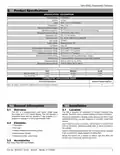
2. Product Specifications
SPECIFICATION DESCRIPTION
Product Models
TCONT202
Product
Size
XR 202
3-3/4” x 6” x 1-1/8 (HxWxD)
Heat / Cool
Configurations
Maximum Number of Stages
Operating Temperature
Shipping Temperature Range
Input Power (DC)
1H, 1C
32°F to 105°F (0 to +41°C) / 90% RH Non Condensing
-20 to 150°F (-29 to +65°C)
Two 1.5V AA Alkaline
Input Power (AC)
20 - 30 VAC, NEC Class ll, 50/60 HZ
18 AWG
Wire Usage
System Modes
Heating, Cooling, Off
Fan Modes
Auto, On
Cooling Setpoint Temperature Range
Heating Setpoint Temperature Range
Temperature Display Range
Minimum Cycle Off Time Delay
Terminal Load
45°F to 99°F, 1°F resolution
45°F to 99°F, 1°F resolution
32°F to 99°F, 1°F resolution
Compressor: 5 minutes, Indoor Heat; 1 minute
1.0A per terminal, 1.5A maximum all terminals combined
32°F to +105°F (0° to +41°C)
-20°F to +150°F (29° to +65°C)
Operating Ambient
Shipping Temperature Range
RATED DIFFERENTIALS
FAST
0.5°F
0.9°F
MEDIUM
0.75°F
1.2°F
SLOW
Heat (@ 6°F/Hr)
Cool (@ 6°F/Hr)
1.9°F
1.7°F
THERMOSTAT APPLICATION GUIDE
Thermostat Applications
Maximum Stages Heat/Cool
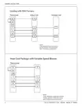
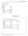
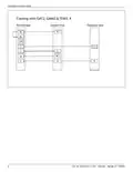
Gas, Oil, Electric, (mV and 24V), Heat Only, Cool Only or Heat/Cool Systems
1/1
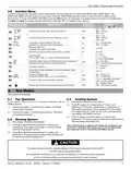
3. General Information
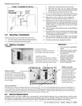
4. Installation
3.1 Overview
4.1 Location
The 202 is designed for installation in climate controlled living
spaces. Place the unit in a central location with good circulation.
The 202 is a programmable push button single stage
thermostat with a 3.5’’ backlit display. The 202 features a
scheduling mode that can operate a 7-day program, 5-1-1
program or operate in a non-programmable mode.
For proper temperature sensing, avoid exposing the 202 to heat
radiated from lamps, sun light, fireplaces or any other radiant heat
source.
3.2 Contents
Avoid locations close to windows, behind doors or alcoves with
poor air circulation, adjoining outside walls, or doors that lead to
the outside.
—
—
—
—
—
1-Thermostat
1-Sub-base
2-Phillips slotted head mounting screws
2-Nylon Drywall Anchors
1-Installation Guide / User Guide
Select a location that prevents the 202 from being directly exposed
to air currents from supply registers or ceiling fans.
Mount the Control on a section of interior wall that does not
contain hot or cold water pipes or duct work.
3.3 Accessories
Wall Cover Plate (BAYCOVR200A)
Pub. No. 18HD51D1-1C-EN 09/2020 Part No. 37-7769005
3
| General | Details |
|---|---|
| Name | TRANE XR202 Programmable Thermostat User Guide |
| Make | Trane |
| Language | English |
| Filetype | PDF (Download) |
| File size | 0.33 MB |


TRANE BAYECON089A Programmable Touch Screen Thermostat Instruction Manual

TRANE XR103 Non-Programmable Heat Pump Thermostat User Guide

TRANE XR102 Non-Programmable Thermostat User Guide

TRANE SC360 Link System Controller and Smart Thermostat Instructions


Fantini Cosmi CH141E Battery Operated Weekly Programming Thermostat Owner’s Manual

Network Thermostat NetX X7 Series Thermostat Instruction Manual

PURGEAR STC-100A Digital Thermostat User Guide

Honeywell Smart Color Touchscreen Programmable Thermostat RTH9590 User Manual

EMOS P5611OT Wireless Thermostat Instruction Manual
tuya TRV603 Smart WiFi Radiator Thermostat Instruction Manual

REPTIZOO TC04 Timing Thermostat Instruction Manual

Honeywell RTH7500 7-Day Programmable Thermostat Installation Guide

Carrier 53DFS250-SL Programmable Digital Thermostat Owner’s Manual

sinope Smart Floor Heating Thermostat TH1310WF Installation Guide