sensi Lite Zigbee Smart Thermostat Installation Guide


Professional
Installation

| General | Details |
|---|---|
| Name | sensi Lite Zigbee Smart Thermostat Installation Guide |
| Make | sensi |
| Language | English |
| Filetype | PDF (Download) |
| File size | 0.24 MB |


sensi 1F87U-42WF Smart Thermostat Installation Guide

sensi 1F76U-22WFB Lite Smart Thermostat User Manual

ST76 Sensi Touch 2 Smart Thermostat Instruction Manual

sensi 1F95U-42WF Series Touch Smart Thermostat User Guide

sensi 1F76U-22WFB Series Lite Smart Thermostat Installation Guide

sensi ST76 Series Touch 2 Smart Thermostat User Manual

sensi ST765470 Thermostat Installation Guide

sensi 1F96U-42WF Series Touch 2 Smart Thermostat Installation Guide

sensi Lite Zigbee Smart Thermostat Installation Guide Overview
Summary of Contents
- Page 1: Page 1
- Page 2: Designed by the pros for the pros. There are a lot of choices when it comes to buying a thermostat. Only one combines 100 years of HVAC experience and the latest connected home technology. Empower your customers to take control of their comfort from anywhere. Connect you to a professional-grade thermostat that you can offer your customers with confidence. Keep you connected with them even after the initial install. Visit sensihelp.com for around-the-clock access to support articles. Instructional downloads and comprehensive support videos are available. Our highly trained Sensi Support Team is available seven days a week.
- Page 3: Easy to install and connect. Sensi is designed to install like a standard thermostat. It gives you the flexibility to connect to your Zigbee or Zwave smart home hub. For the latest smarthome compatibility, check sensihelp.com/smarthome. Update smart home compatibility site.
- Page 4: What's in the box? - Sensi Lite smart thermostat – Zigbee + Zwave - Screws and anchors - Welcome guide - Wire labels - (2) AAA batteries Things you’ll need: - The homeowner’s compatible iOS or Android device with the smart hub app - Your smart hub network name and password - Medium Phillips screwdriver - Installation QR code (on back of welcome guide and thermostat)
- Page 5: Conventional single-stage or multi-stage systems (no heat pump) Thermostat System configuration Dots indicate phased relationship Common connection required on heat-only, cool-only or heat pump systems.
- Page 6: Common wire (24V) 1st-stage auxiliary/emergency heat (2nd-stage heat) Indoor blower (fan) 1st-stage heat and cool (compressor) Heat pump changeover (reversing valve) connection (configure as O or B in the installer menu) Multi-stage not available for heat pump configurations 24VAC power from HVAC system (Reversing valve setup) O or B
- Page 7: Configure the thermostat to the appropriate system type. To get into the configuration menu, press and hold the three dots on the thermostat for 8 seconds. Navigate options within a step by tapping the up/down arrows. Confirm selection and move to the next step by tapping the three dots. Step 1: Select your outdoor equipment. Step 2: Select your indoor equipment. Step 3: Select additional configuration for O/B terminal. Step 4: Select fan settings.
- Page 8: System testing Once the thermostat is installed and properly configured, you can test the equipment using the following steps. Cooling system Tap the 3 dots on the thermostat until you select the cool mode. Tap and adjust the setting to 1° below the current room temperature. The blower should come on immediately on high speed, followed by cold air circulation. The word ON will also appear below the icons on the thermostat display. Note that there can be up to a 5-minute delay for this process. Tap and adjust the setting to 1° above the current room temperature. The cooling system should stop operating. If you encounter any issues while testing the equipment, refer to the troubleshooting actions on page 16.
- Page 9: Heating system Tap the 3 dots on the thermostat until you select the Heat mode. Tap and adjust the setting to 1° above the current room temperature. The heating system should begin to operate. For heat pumps with auxiliary, tap and adjust the setting to 3° above the current room temperature. Press and adjust the setting to 1° below the current room temperature. The heating system should stop operating. Auxiliary system (only for heat pumps with auxiliary) Tap the 3 dots on the thermostat until you select the AUX mode. This bypasses the heat pump and runs auxiliary-only heat. Tap and adjust the setting to 1° above the current room temperature. The auxiliary heating system should begin to operate. Tap and adjust the setting to 1° below the current room temperature. The auxiliary heating system should stop operating.
- Page 10: Troubleshooting No heat/no cool/no fan (common problem) Blown fuse or tripped circuit breaker Replace fuse or reset breaker. Furnace power switch to OFF Furnace blower compartment door panel loose Tighten connections. No heat Thermostat not set to heat Set thermostat to heat. Verify thermostat and system wires are securely attached. Diagnostic: Set system mode to heat and raise the setpoint above room temperature. No cool Thermostat not set to cool Set thermostat to cool. Verify thermostat and system wires are securely attached.
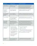
- Page 11: Symptom: Heat, Cool or Fan Runs Constantly Possible cause: Possible short in wiring, thermostat, heat, cool or fan system Corrective action: Check each wire connection to verify they are not shorted or touching other wires. Try resetting the thermostat by pressing and holding all three buttons on the thermostat. Thermostat display & thermometer disagree Thermostat display requires adjustment Display can be adjusted +/-5° using the Temperature Offset in Sensi app. Humidity display & hygrometer disagree Humidity display requires adjustment Display can be adjusted in 5% increments +/- 25% using the Humidity Offset in the Sensi app. Display is blank The AAA batteries might need to be replaced or you may need a common wire (c-wire) Replace the AAA batteries on the back of thermostat or attach a common wire (c-wire). Furnace (Air Conditioner) cycles too fast The location of the thermostat and/or the size of the heating system may be influencing the cycle rate Digital thermostats provide precise control and cycle faster than older mechanical models. “Call for Service” appears on the screen Heating or cooling system is not able to heat/cool the space to within 5 degrees of the setpoint within 2 hours See corrective action for “No Heat” or “No Cool.” Replace thermostat. Fan turns on randomly The fan has been set to run occasionally in the configuration menu Enter the configuration menu and make sure the fan run time percentage is OFF.
- Page 12: Warnings Failure to read and follow all instructions carefully before installing or operating this control could cause personal injury and/or property damage. For California residents: This product contains a chemical known to the state of California to cause cancer and birth defects and other reproductive harm. Do not use on circuits exceeding specified voltage. Higher voltage will damage control and could cause shock or fire hazard. Thermostat installation and all components of the control system shall conform to Class II circuits per the NEC code. This product does not contain mercury. However, this product may replace a product that contains mercury. Mercury and products containing mercury must not be discarded in household trash.
- Page 13: FCC regulations state that this device complies with part 15 of the FCC Rules. Operation is subject to two conditions: it may not cause harmful interference and must accept any interference received. Changes or modifications not approved by the manufacturer could void the user's authority to operate the equipment. The antenna used for this transmitter must not be co-located or operating with any other antenna or transmitter. This equipment has been tested and complies with the limits for a Class B digital device. These limits provide reasonable protection against harmful interference in a residential installation. The equipment generates, uses, and can radiate radio frequency energy. If not installed and used according to the instructions, it may cause harmful interference to radio communications. There is no guarantee that interference will not occur in a particular installation.

Danfoss RA2000 TRV Thermostat Instructions

Homematic IP HmIP-WTH-B Wireless Wall Thermostat Instruction Manual

beca BAC-003 Series WiFi Thermostat Fan Coil

Drayton RF710 Digital Wireless Room Thermostat Installation Guide

BEOK TGR85-EP Mirror Touch Screen Underfloor Heating Thermostat User Guide

ENGO CONTROLS EFAN-24W, EFAN-24B Fan Coil Thermostat User Guide

REGIN RCFD-230C Fan Coil Room Thermostat Instructions

DAIKIN ONE+ Smart Thermostat User Manual

ENGO CONTROLS E901RF Series Programmable Thermostat User Guide

Honeywell FocusPRO P200 Series Programmable Thermostat Installation Guide