Home > KINGHOME > KINGHOME WK-010WC1 Smart Thermostat Owner’s Manual

KINGHOME WK-010WC1 Smart Thermostat Owner’s Manual

Thermostat WK-010WC1  
App Guide  
KINGHOME PLUS  
GeneralDetails
NameKINGHOME WK-010WC1 Smart Thermostat Owner’s Manual
MakeKINGHOME
LanguageEnglish
FiletypePDF (Download)
File size0.52 MB
Download PDF
1 Star2 Stars3 Stars4 Stars5 Stars (1 votes, average: 5.00 out of 5)
Loading...
KINGHOME WK-010WD1 Smart Thermostat Owner’s Manual

KINGHOME WK-010WC1 Smart Thermostat Owner’s Manual
Get the free PDF manual for the KINGHOME WK-010WC1 Smart Thermostat Owner’s Manual and access setup steps, usage instructions, and troubleshooting tips. 👉 View online or download now to keep your thermostat running smoothly!

KINGHOME WK-010WC1 Smart Thermostat Owner’s Manual Overview

Summary of Contents

  • Page 1: Thermostat WK-010WC1 App guide KINGHOME PLUS
  • Page 2: Thank you for selecting RXU product. Please read this instruction manual carefully before installing and using the product. This appliance is not intended for use by persons with reduced physical, sensory or mental capabilities, or lack of experience and knowledge, unless supervised. This instruction manual is a universal manual; some functions are only applicable to particular products. All illustrations and information in the instruction manual are for reference; control interface should be subject to actual operation. We will continuously conduct improvement and innovation. If there is adjustment in the product, please refer to the actual product. For installation, moving, or maintenance, please contact our designated dealer or local service center for professional support. Users should not disassemble or maintain the unit by themselves, otherwise it may cause relative damage.
  • Page 3: Safety notices should be adhered to. Installation includes dimensions and components of the thermostat. Instructions for thermostat wiring terminals are provided. There are specific requirements for the installation position of the thermostat. The installation process for the thermostat is detailed. Disassembly instructions for the thermostat are included. An introduction to the display is provided. The thermostat homepage display and button instructions are explained. Operation instructions cover settings for unit on/off and mode. Temperature adjustment and schedule function settings are outlined.
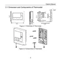
  • Page 4: Owner's manual Dimension and components of thermostat Figure 2-1 shows the dimension of the thermostat. Figure 2-2 illustrates the components of the thermostat.
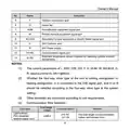
  • Page 5: Owner's manual Introduction of components Thermostat Tapping screw ST3.9×25 MA Mounted plate of thermostat Instruction of thermostat wiring Wiring terminal of thermostat Instruction of thermostat wiring terminal Port of refrigerant detection abnormal signal sent by the unit Economizer or fresh air equipment signal port
  • Page 6: Owner's manual Outdoor compressor gear Indoor fan Humidification equipment signal port Primary furnace equipment signal port Secondary furnace equipment or electric heater signal port 24V common wire 24V power supply Communication signal port Extended temperature sensor interface for detecting outdoor ambient temperature.
  • Page 7: Owner's Manual Cord length Cord type Cord size (mm²) When the installation environment of the thermostat is in strong magnetic or strong interference, it is necessary to use a shielded cord. Please do not install the thermostat in the position where it is wet or likely to be splashed with water. Please do not install the thermostat near high-temperature objects or under direct sunlight. Before installation, please cut off the power supply of strong current wire inside the wall; it is not allowed to install under electrified status. The thermostat should only be installed indoors, and its working temperature range is 0°C~50°C. For installation steps of the thermostat, please refer to the following sketch map; brief instructions are as below.
  • Page 8: Owner's Manual Align the thermostat mounting plate at the installation holes and then use the self-tapping screw ST3.9×25 MA to fix the thermostat mounting plate with the installation holes on the wall. Use a slot screwdriver to insert the wire protector pressing hole of wiring terminal, and then insert the control wire into the wiring hole of the wire terminal. Pull the tool out from the wire protector pressing hole and connect all control wires according to this way. Pay attention not to connect the heavy current. Set the thermostat with the thermostat mounting plate together to complete the installation.
  • Page 9: Owner's manual Disassembly of thermostat Disassembly for thermostat is as below.
  • Page 10: Introduction to display Thermostat homepage display and button instruction The contents in the display shown above will not exist at the same time. The figure shows all the displayed contents just to facilitate describing where they will be displayed. Table 3.1.1 Thermostat homepage display and button instruction Display current time Display current weekday WiFi function (It displays only when the thermostat has WiFi function)
  • Page 11: Owner's Manual It is displayed to remind that the filter shall be cleaned. It is displayed when the buttons are locked. It is displayed when the battery is low. It is displayed to remind which equipment is in use: Heat pump / Furnace. Display the set temperature in the current mode. Keep the current set temperature and Hold will be displayed when the set temperature of the schedule is not executed. On the homepage, you can enter the Menu page by pressing this button. Display when unit is running. Display current operation mode. It is displayed when the schedule is enabled.
  • Page 12: Owner's Manual Fan mode displays the current fan mode and the relative ambient humidity and temperature. Indoor ambient humidity and temperature are monitored by the thermostat. Humidification equipment status is indicated when the function is enabled. Intelligent heating predicts energy-saving heat sources based on the external environment. The word smart is displayed when the intelligent heating function is activated. When the thermostat receives multiple control instructions, one shall prevail. Settings for unit on/off and mode can be adjusted using the Mode button. The mode can be switched in a specific sequence including options like Cool, Dehum, AUX Heat, and Auto. The operation instructions detail the mode switching sequence for different settings.
  • Page 13: Owner's Manual Please set the ODU function setting according to the ODU type. Press the Fan button on the homepage to switch the Fan mode. Fan mode switching sequence: Auto → On → Auto, High → Medium → Low → Auto → High. ON: The fan runs at some certain speed all the time. AUTO: The fan will be turned on or off as the change of the set and ambient temperature. High: Under RS485 control mode, it always runs at the highest fan speed. Medium: Under RS485 control mode, it always runs at medium fan speed. Low: Under RS485 control mode, it always runs at low fan speed.
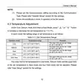
  • Page 14: Owner's Manual Please set the Communication setting according to the Communication Type. Under dehumidification mode, it operates at low fan speed. Under Cool, Dehum, Heat, AUX heat or Auto Mode, press the button to increase or decrease the set temperature by 1°C (°F). In each mode, the setting range of set temperature is specified. The lower limit can be set in Cool mode, Dehum mode, and the upper limit can be set in Heat mode and Aux Heat mode. The temperature range for Cool mode is 10~30°C (50~86°F). The temperature range for Dehum mode is 10~32°C (50~90°F). The upper limit for Dehum mode is 16~32°C (61~90°F). The temperature range for Heat mode and Auto mode is 10~32°C (50~90°F). Please refer to the User Setup section for the settings.
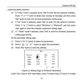
  • Page 15: Owner's Manual Schedule function is used to set specific time of the week to execute a specific mode. Under unit off mode, hold on pressing Function button 2 to enter the setting selection page of timed mode. On the setting selection page of timed mode, press the buttons to select the timed mode. Instructions of timed mode include adjusting program schedule parameters for each day of the week. The 7 Day mode allows for circular execution every week after setting. Adjust program schedule parameters on weekdays and weekends for circular execution. The 1 Week mode also allows for circular execution every week after setting. Select the schedule timed mode that you want to set and press Set to enter.
  • Page 16: Owner's Manual If 7 Day mode is selected, press Set to enter the day selection interface. If 5-2 mode is selected, press Set to enter the day selection interface. If 1 Week mode is selected, press Set to enter the schedule parameters setting page directly. Press < or > button to select the parameters. Press or button to adjust the parameters. Press Set button to save the settings. Under Cool, Heat or AUX Heat Mode, press Function button 2 to enable.
  • Page 17: Owner's Manual If Week Sched. is displayed on the homepage, it means that the schedule function is opening. If the schedule has been executed, the executed period name will be displayed. After the schedule is enabled, adjusting the set temperature will display Hold above the set temperature. The schedule function is still running, but the set temperature is not running according to the set parameter. The actual adjusted value will prevail until the next schedule period is reached. When the next schedule period is reached, Hold will be cleared and the schedule will run according to the set parameters.
  • Page 18: Owner's Manual If Week Sched. is not displayed on the homepage and Hold is not displayed above the set temperature, it means the schedule function is off. App's schedule and thermostat schedule are executed separately and they are valid according to the time sequence. When any one of App's schedule or thermostat schedule is valid, schedule.
  • Page 19: Owner's Manual When any one of the app's schedule or thermostat schedule is valid, change the set temperature and the thermostat will display the reminder of Hold. Child-lock function allows the liquid crystal screen to display a specific message. Press specific buttons simultaneously for 5 seconds to enter or exit the child-lock function. Under child-lock status, no response for pressing any buttons. The unit will memorize the child-lock status after power failure and re-energizing. The app can be used to control the thermostat. Scan the QR code or search for the app in the application market to download and install it. When the app is installed, register the account and add the device for long-distance control. Reset WiFi of the thermostat at first when using the app for the first time. The WiFi icon flickering indicates that the reset is successful.
  • Page 20: Owner's Manual If the device is offline or the router's name and password have been changed, please reset WiFi and add the device again. WiFi networking performance is related to the distance between the thermostat and the router and the obstacles between them. During the installation process, the distance between the thermostat and the router should be as close as possible, and the obstacles should be as little as possible. If the WiFi signal is not good, use the WiFi signal enhanced router. When the thermostat is powered by the battery, the WiFi function is unavailable and cannot control the unit through the App. When the thermostat is powered by the unit, the WiFi function can be used normally.
  • Page 21: Owner's Manual Parameter Settings Menu Page Press Menu button on the homepage to enter the Menu page. On the Menu page, press ∧ or ∨ button to move the cursor for selecting User Function, User Setup, Installer Setup or Information Search. Press Set button to enter the corresponding page. User Function Settings On the Setting page, press ∧ or ∨ button to move the cursor for selecting the parameter to be set. Press Set button to select the parameter to be set. Press ▲ or ▼ button to select the parameter value, and then press Set to save the setting.
  • Page 22: Owner's Manual The detailed user function list is as follows. User parameter list includes dual fuel type and humidifier settings. The Smart mode of dual fuel function requires WiFi connection. The target humidity value can be set only when the humidifier function is ON. On the System page, use the cursor to select the parameter to be set. Press the Set button to select the parameter to be set. Press ▲ or ▼ to select the parameter value, then press Set to save. Press Menu button to return to the Menu page. If there is no operation within 20 seconds, it will return to the homepage automatically. When a certain parameter cannot be set, it will be displayed in gray.
  • Page 23: Owner's Manual System Parameter List Clock Format Set the clock format. Press Set button to enter the setting page of time and date. Daylight Saving Time Set summer time/winter time. Note: only applicable when the power is not supplied by battery. Backlight Set if the unit on/off status is memorized during power failure. Temperature Unit Set the unit of temperature. Filter Cleaning Reminder Set the filter cleaning reminder time. Language Set Language: English/French. Synchronize Time with App Note: The thermostat can only be set when it is connected to WiFi. WiFi Reset Note: only applicable to models with WiFi function. Min Cool Setpoint Set the lower limit for the set temperature in cooling. Max Heat Setpoint Set the upper limit for the set temperature in heating.
  • Page 24: Owner's Manual When the thermostat is connected to WiFi, and the parameter Synchronize App time is set to YES, the time of the thermostat is synchronized to the App time. On the System page, press the button to move the cursor for selecting the parameter to be set, and press Set button to select the parameter to be set. Press Menu button to return to the Menu page. If there is no operation within 20 seconds, it will return to the homepage automatically. When a certain parameter cannot be set, it will be displayed in gray. Under ON mode, all parameters cannot be set, but can be inquired. Table 5.4.1 Installation Parameters List This parameter is fixed to Primary. Set the unit control mode. The factory default is 24V communication mode. If you need to change this setting, you need to consult the manufacturer's technical support.
  • Page 25: Owner's manual Set the function of outdoor unit. Only can be set under unit off mode. Set cooling/heating energization four-way valve. Set the function of indoor unit. Set the starting time of electric heating in heating mode. Set the upper limit of the starting temperature of the electric heating in heating mode. Set the starting temperature difference of electric heating in heating mode. Set electric heating to continue to operate before unit stops when reaching the temperature point. Indoor unit type. Max activate temperature for AUX.
  • Page 26: Owner's Manual Set Dual Fuel changeover outdoor temperature Set the time of Dual Fuel changeover furnace Set the minimum operation time of furnace Sets the indoor ambient temperature compensation value DualFuel Switch Timer Furnace Min On Time Set Cooling temperature difference under Auto Mode Set the delayed start time for the compressor Set the minimum operation time of compressor Delayed shutdown time of indoor fan
  • Page 27: Owner's manual Restore factory settings can only be set under unit off mode. After the factory setting is restored, the parameters in the Installer Setup list are restored to the default values. In the inquiry interface, you can inquire the outdoor ambient temperature, product version, installer name, installer contact, historical errors, indoor parameters, and outdoor parameters. The latest 10 historical errors can be inquired. This information can only be queried when the communication is set to RS485, and is only used by maintenance personnel. When the S1/S2 interface is not connected to the outdoor ambient temperature sensor, the outdoor ambient temperature inquiry display is fixed to -100°C/-148°F.
  • Page 28: Owner's manual Display of errors When an error occurs in the system, the indoor ambient temperature display area will show an error code. If multiple errors occur simultaneously, the error codes will display circularly. When an error occurs, turn off the unit and seek professional maintenance. The following figure refers to the indoor temperature or humidity sensor. Error code list includes various error types such as refrigerant leakage protection and sensor errors.
  • Page 29: Owner's Manual Error Code Indoor ambient temperature is too high Indoor ambient temperature is too low Communication error of thermostat Compressor high pressure protection Compressor low pressure protection Compressor discharge temperature protection Overload protection Discharge temperature sensor error Outdoor ambient temperature sensor error
  • Page 30: Owner's manual Error codes High DC bus voltage AC current protection (input side) IPM abnormality Compressor overcurrent Communication error between main control and drive High temperature of radiating sheet or IPM module or PFC module Error of drive memory chip Abnormality of AC input voltage
  • Page 31: Owner's manual Error code AC contactor protection Temperature drift protection Sensor connection protection Inverter outdoor fan drive IPM module protection Inverter outdoor fan startup failure Inverter outdoor fan overcurrent protection Indoor ambient temperature sensor error Evaporator inlet pipe temperature sensor error
  • Page 32: Owner's manual Error code Indoor unit jumper cap error Indoor fan error In the event of an EA/FE fault, the thermostat lights up the backlight and gives a buzzer alarm. The user can cancel the backlight and buzzer alarm by pressing the Mode button on the homepage, but the code display can only be canceled after the fault is eliminated. Operation instructions and notices of batteries Installation of batteries Install two AA dry batteries (1.5V) according to the following figure.
  • Page 33: Owner's Manual Replacement of batteries Replace the batteries when the low power icon is displayed. If only the batteries are used to supply power to the thermostat, ensure that the batteries work longer; if there is no operation within 10 seconds, the display screen will temporarily extinguish. Press the Function button 2 to wake up the screen before operation again. The batteries only guarantee normal display; in this case, WiFi does not work and the unit cannot be controlled. Selection of extended temperature sensor The precision of the temperature sensor shall be ±1°C. Before use, measure the resistance at both ends of the temperature sensor with an ohmmeter. Check if the temperature sensor is in good condition by referring to the provided resistance table.
  • Page 34: Owner's manual Outdoor ambient temperature Resistance (KΩ) °C °F
  • Page 35: Owner's Manual Outdoor ambient temperature Resistance (KΩ) This product contains FCC ID 2ADAP-GRJWB05J10 and IC 12478A-GRJWB05J10 CAN ICES-003(B)/NMB-003(B). This device complies with Part 15 of the FCC Rules. Operation is subject to the following two conditions: (1) this device may not cause harmful interference, and (2) this device must accept any interference received, including interference that may cause undesired operation. Changes or modifications not expressly approved by the party responsible for
  • Page 36: Owner's Manual Compliance could void the user's authority to operate the equipment. This equipment has been tested and found to comply with the limits for a Class B digital device, pursuant to Part 15 of the FCC Rules. These limits are designed to provide reasonable protection against harmful interference in a residential installation. This equipment generates, uses and can radiate radio frequency energy. If not installed and used in accordance with the instructions, it may cause harmful interference to radio communications. There is no guarantee that interference will not occur in a particular installation. If this equipment does cause harmful interference to radio or television reception, the user is encouraged to try to correct the interference. Reorient or relocate the receiving antenna. Increase the separation between the equipment and receiver. Consult the dealer or an experienced radio/TV technician for help.