Home > GENERAL LIFE > GENERAL LIFE HT300 RF Digital Room Thermostat User Manual
GENERAL LIFE HT300 RF Digital Room Thermostat User Manual
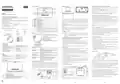


ProductDisplayLayout
BATTERY PLACEMENT
PAIRING THE ROOM THERMOSTAT AND THE RECEIVER
ENGLISH
Primarily press the sync button of the Receiver for 2 seconds and see blinking
greenlight oftheReceiver.
7
8
1
2
While yourdeviceis turned off, pressand hold the"On/Off" button for 3 seconds.
DIGITAL ROOM THERMOSTAT
Pressthebutton until the“
” menu appears.
Press the “Up” or “Down” button of your Room Thermostat while the LED is
flashing green.
generallife.com.tr
9
3
10
11
Ifthepairing issuccessful, thegreenflashing LEDon theReceiverwillbe steady.
Receiverand Room Thermostathavebeen pairedto eachother.
4
5
6
SERIES:
MITRA, ARUNA, CERES, GAIA, ILLONA
ROOM THERMOSTATTEMPERATURE CALIBRATION
Temperature sensors which are used in Room Thermostats are highly sensitive.
You may need to calibrate your Room Thermostat if you would like to get the same
temperaturevalueswithother thermometersin yourliving space.
HT300 RF/HT300S RF USER MANUAL
1
2
3
4
5
6
7
8
9
Hour Indicator
GENERAL SPECIFICATIONS
HT300 RF/HT300S RF is
Press the screwdriver forward from the space at the bottom of the Room
Thermostat, bend the tabs and separate the front cover. Insert 2 new AAA alkaline
batteries in the battery housing with the correct battery direction. Replace both
batteries at the same time. Align the front part of your Room Thermostat with
corresponding slot on the back, and then push gently until the thermostat snaps
into place.
While yourdeviceis turned off, pressand hold the“On/Off“ button for 3 seconds.
Press the "On/Off" button until the “ ” menu appears. In order to see the
Room Temperature
Economy Mode
Comfort Mode
a
wireless room thermostat. The user can get more
comfortable and economic heating/cooling by adjusting the room thermostat with
therequiredtemperature.
desired temperature, set the temperature difference by pressing the
“Temperature Adjustment Buttons”. This value can be arranged between “-8° C"
Holiday Mode
Weekly Program Mode
Day Indicator
Dailyand WeeklyProgramming
and “+8° C".
DifferentMode Options (Comfort, Economy, Holiday)
In order to save the settings and exit, press the "On/Off" button until the device
turns off.
Heating Calibration
ON/OFFControl
WirelessConnection
Alkaline Battery
Low Battery Warning: When the “
” icon appears on the screen, it means “low
Battery Indicator
Set Temperature
Heating Indicator
Heating/Cooling Option
TPIAlgorithm
battery warning”. It is recommended to replace the batteries when this warning
appears.
Note:Recommended temperaturecalibration is “0.0°C”.
PreciseTemperatureMeasurement
Warning: When the product is not used for a long period (more than 15 days),
remove the batteries. Otherwise, malfunctions that may occur would be out of
warranty. Pleasethrowyourdead batteriesinto thewastebin for batteries.
FACTORY SETTINGS RESET
10
- If the Heating Indicator is blinking, the heating unit is working.
- If the Heating Indicator is steady, the heating unit is not working.
Cooling Indicator
HT300 RF/HT300S RF and EQUIPMENTS
You can reset your Room Thermostat to its default factory settings. This operation
resets the mode temperature values, calibration setting and heating/cooling
modes to factory setting. In orderto resetyourRoom Thermostatto factory setting:
Room Thermostat
Holder
11
- If the Cooling Indicator is blinking, the cooling unit is working.
- If the Cooling Indicator is steady, the cooling unit is not working.
RECEIVER PLACEMENT
While yourdeviceis turned off, pressand hold the“On/Off” button for 3 seconds.
Pressthe“On/Off” button untilthe“ ” menu appears.
While in the “ ” menu, select the “ ” option by using the “Up” or “Down”
buttons and pressthe“On/Off” button.
Your devicewillbe turned off and resetto factory settings.
The important things to note for the Receiver placement are
avoiding physical contact between the Receiver and
heating/cooling unit, and protecting it against materials
such asliquid, dust etc.
RECEIVER
1-Manual Operation Button: Deactivates the
Receiver and allows you to use heating/cooling
unit manually.
1
2
3
Dowels and Screws
Receiver
DAY AND HOUR SETTINGS
2-Pairing Button: Allows pairing the Receiver
with the Room Thermostat.
3-Receiver LED Light
4-Receiver Power Cable Input
5-Heating/Cooling Unit Connection Cable Input
The devices should be placed in order to minimize the damage to the received and
transmittedsignals bypayingattentiontothefollowingpoints;
While your Room Thermostat is on, keep pressing the “Weekly Program” button
for 3 seconds.
The devicesshould not be mounted on metalsurfaces.
At the first screen that appears, hour part will be blinking. You may set the time
withthe“Up” and“Down” buttons.
The devices should not be installed close to electrical cables and electronic
equipment such ascomputers and televisionunits.
After setting the time, the “Heating & Cooling Option” button needs to be pressed
once. For minute setting, minute part will be blinking. You mayset the minute with
the“Up” and“Down” buttons.
The devices should not be installed near large metal structures or other building
materialsusing finemetalmeshes such asspecialglass or specialconcrete.
Distance between the Room Thermostat and the Receiver should not exceed 20
metersor 2 floors.
TECHNICAL DATA
Room Thermostat
After setting the minute, the “Heating & Cooling Option” button needs to be
pressedonce to setthedayof theweek.
Dimensions
Operating Current
85mm / 125mm / 20mm
3V DC (2 x AAA alkaline battery)
0.1oC
(5oC) – (30oC)
Receivermust be installed atleast50cmawayfromtheheating/cooling unit.
Mondayhas setasthefirstdayof theweekand indicated withnumber“1".
Numbers indicate the following days respectively 2-Tuesday, 3-Wednesday, 4-
Thursday, 5-Friday, 6-Saturdayand 7-Sunday
4
5
RECEIVER LED DESCRIPTIONS
Temperature Measurement Accuracy
Operating Temperature Range
Battery Life
RECEIVER SETUP
Steady Red
Receiver has power but Receiver and Room Thermostat
First, shut down your heating/cooling unit and your heating/cooling unit's power
sourcewithallelectricalcurrent(fuse, socketetc.)
When setting is done, you may exit by pressing the “Weekly Program” button for 3
seconds.
are not paired.
1 Year (2 x AAA)
(-10oC) – (+50oC)
(-20oC) – (+60oC)
Blinking Green
Steady Green
Waiting for pairing signal from the Room Thermostat.
Receiver and Room Thermostat are paired.
Heating/cooling unit is not operating.
Operating Temperature
Storage Temperature
As shown in the connection diagram, connect one end of the heating/cooling unit
connection cableto theCOMand theother to theNO input of theReceiver.
Connect the other ends of the cable -which you connected to the Receiver- to
room thermostat connection terminal as shown in your heating/cooling unit's
user manual.
MODE SETTING
MODES
3 Short Orange Blinking Operate the heating/cooling unit signal has reached to
the Receiver.
Receiver
Steady Orange
Heating/cooling unit is operating.
You must first connect the Receiver power cable to the Receiver and then to the
fuse which theheating/cooling unit is connected.
Dimensions
Operating Current
Relay NO Switching Current
90mm / 90mm / 25mm
230V AC
PRESET MODES
WEEKLY
PROGRAM
MODE
MANUAL MODE
3 Short Green Blinking
Shut the heating/cooling unit down signal has reached
to the Receiver.
After completing the cable connection process, firstly turn on your fuse and then
yourheating/cooling unit.
7A (240VAC – Resistive Load)
10A (120VAC – Resistive Load)
(-20oC) – (+60oC)
Blinking Orange
Blinking Red
Heating/Cooling unit operates in manual mode.
Receiver did not get any signal from the Room
Thermostat for 22 minutes or longer.
Heating/cooling unit has shut down.
Comfort
Mode
Economy
Mode
Holiday
Mode
Storage Temperature
By pressing the Receiver's manual usage button for 2 seconds, you should see
the Orange Light blinking on the Receiver. In this way, after making sure that the
heating/cooling unit is operating, press the same button again for 2 seconds and
seethattheOrange LEDturns off.
Your Room Thermostat has 5 different modes. 3 of them (Comfort, Economy and
Holiday Mode) are preset modes. Other modes are manual mode and weekly
programmode.
ROOM THERMOSTAT
ButtonFunctions
ROOM THERMOSTAT PLACEMENT
Room Thermostat needs to be placed in the room which is used most frequently.
For instance; living room or lounge. Placing the Room Thermostat in a spot that
have air circulation like entrance of a room or side of window should be avoided.
Also anywhere close to heating/cooling units such as radiator, stove and spots
which get direct sun lights would not be suitable. Room Thermostat needs to be
located above the floor 150 cm height. Few trials may be made to find the most
convenientspot.
Setup theRoom Thermostatto pair theReceiverwiththeRoom Thermostat.
In preset modes, temperature values are based on user's choices which have been
set in the beginning. Manual mode allows the Room Thermostat to operate within
the temperature which is required and set directly by user. Weekly Program mode
continues to workaccordingto theweeklyschedule determined bytheuser.
In orderto change thetemperaturevaluesof presetmodes:
RECEIVER WIRING DIAGRAM
AC
COM
NO
(230V)
Press and hold the “Mode” button for 3 seconds while your Room Thermostat is
on.
Comfort Mode temperature value will appear. You may adjust the temperature
valueof Comfort Mode bypressingthe“Up” and “Down”buttons.
When setting is done, you may adjust the temperature value of Economy Mode
withthe“Up” and “Down”buttons bypressingthe“Mode”button again.
You mayexitthesettingscreenbypressingthe“Mode”button 3 seconds.
In orderto change the manual mode temperature, pressthe “Up” or “Down”button
while in the main screen. The Room Thermostat will switch to Manual Mode once
pressedthe“Up” or “Down”button.
1
4
2
3
5
6
min. 20 cm
1
2
3
4
5
6
On/Off Button
Heating & Cooling Option
Weekly Program Button
HEATING/COOLING UNIT
Temperature Adjustment Button (To Decrease)
Temperature Adjustment Button (To Increase)
Mode Button
Warning!
You maypressthe“Mode”button to switchto theother modes.
Operations within the heating / cooling unit or the electrical installation must be
carriedout byprofessionally qualified persons.
1
2
3
4

| General | Details |
|---|---|
| Name | GENERAL LIFE HT300 RF Digital Room Thermostat User Manual |
| Make | GENERAL LIFE |
| Language | English |
| Filetype | PDF (Download) |
| File size | 2.15 MB |


GENERAL LIFE HT330S RF Room Thermostat User Manual

GENERAL LIFE FH103S Underfloor Heating Thermostat User Manual

GENERAL LIFE HT250 RF Digital Room Thermostat User Manual

GENERAL LIFE FH104S Underfloor Heating Thermostat User Manual

GENERAL LIFE ARUNA 302S Digital Room Thermostat User Manual

GENERAL LIFE FH250S Underfloor Heating Thermostat User Manual

GENERAL LIFE FC220 Digital Fan Coil Thermostat User Manual

GENERAL LIFE HT220S RF Digital Room Thermostat User Manual

GENERAL LIFE 270S RF Room Thermostat User Manual

GENERAL LIFE 270 Wireless Room Thermostat User Manual

GENERAL LIFE HT300 RF Digital Room Thermostat User Manual Overview
Summary of Contents
- Page 1: Product display layout Battery placement Pairing the room thermostat and the receiver Press the sync button of the receiver for 2 seconds and see blinking green light of the receiver. If the pairing is successful, the green flashing LED on the receiver will be steady. Temperature sensors used in room thermostats are highly sensitive. You may need to calibrate your room thermostat to match other thermometers in your living space. You can reset your room thermostat to its default factory settings. The important things to note for the receiver placement include avoiding physical contact with the heating/cooling unit. Room thermostat needs to be placed in the room most frequently used, avoiding areas with direct sunlight or close to heating/cooling units.
- Page 2: You may set the operating schedule of your room thermostat with a weekly program. The warranty period starts from the invoice date and is warranted against manufacturing defects for 2 years. Your room thermostat takes the average room temperature of the last 40 seconds as a basis. With the TPI algorithm, it learns how long it takes to reach the desired room temperature and how this temperature is maintained. Seven different temperature values can be set for each day in weekly programming. In order to set the weekly schedule, press and hold the “Weekly Program” button for 3 seconds while your room thermostat is on. If the placement of the TPI room thermostats is changed, the learning process will restart. If the TPI room thermostats are de-energized, the learning process will restart. The customer can make complaints and appeals to consumer courts or consumer arbitration committees. The warranty document must be kept by the customer during the warranty period.

Danfoss RT 9E Thermostat Installation Guide

SIEMENS RDG400 Room Thermostat Instruction Manual

EPH CONTROLS eTRV-HW Smart Hot Water Thermostat Instruction Manual

beok BOT-T9N-WIFI Room Thermostat Instruction Manual

Danfoss ECtemp 330 Electronic Thermostat Installation Guide

FURRION FACW10ESSA-BL Standard Single Zone Wall Thermostat User Guide

SKYTECH 5320P Programmable Thermostat Fireplace Remote Control Instruction Manual

TIOEVO0003 TEVO Wireless Thermostat User Manual

AFRISO RT 10 D 230 Room Thermostat Instruction Manual

White Rodgers 1F85CA-0471 Blue Universal Thermostat Instruction Manual