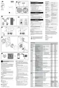
ELKO EKO50107, EKO50108 Matter Thermostat Installation Guide


Floor sensor installation site
no sv
en
Technical data
For reliable operation, the floor sensor must be pro-
tected against moisture, mechanical stresses and
temperature fluctuations.
The following should therefore be taken into account
when considering the installation site:
2
3
fi
Nominal voltage:
Maximum current rating
Resistive load:
AC 230 V ~, 50 Hz
ELKO One
max. 16 A, 3680 W
max. 4 A
Inductive load:
• Install in the middle of the loops of the underfloor
heating unit.
Standby:
max. 0.5 W
A
B
C
Connecting terminals:
Screw terminals for
max. 2.5 mm², 0.5 Nm
• Lay the sensor cable in a plastic tube with an inside
diameter of at least 16 mm.
Neutral conductor:
Required
A
Ambient operating tem-
perature:
• Fix tape to the end of the tube and cut a slice so
that condensation water can come out of the tube.
0 to 40 °C
Relative humidity:
IP rating:
max. 90%, non-condensing
IP21
EKO50107
EKO50108
• Ensure that tube corners are not too tight as cor-
ners affect installation of the sensor cable.
Temperature accuracy:
max. ±0.5 °C (across the range
of 4 to 30 °C)
Electrical connections
DANGER
Temperature measurement
resolution:
0.5 °C
1
Display:
7x5 dot matrix, additional 5 LEDs
IEEE 802.11 b/g/n 2.4 GHz
WPA-PSK / WPA2-PSK
2.401 GHz to 2.483 GHz
B C
Wi-Fi® standard:
Wi-Fi® security:
Operating frequency:
HAZARD OF ELECTRIC SHOCK, EXPLOSION,
OR ARC FLASH
Safe electrical installation must be carried out only
by skilled professionals. Skilled professionals must
prove profound knowledge in the following areas:
Max. radio-frequency power
transmitted:
< 100 mW
4
Floor sensor types:
2k, 10k, 12k, 15k, 33k, 47k
(Thermistor resistance values in
Ohm. Nominal value at 25 °C)
• Connecting to installation networks.
• Connecting several electrical devices.
• Laying electric cables.
Protection Class:
II
• Safety standards, local wiring rules and
regulations.
Working voltage:
230 V
III
Over-voltage category:
Rated impulse voltage:
Pollution degree:
Failure to follow these instructions will result in
death or serious injury.
4 kV
2
CTI rating of insulation
components:
DANGER
175 V
Material group:
IIIa (based on CTI value)
1.B
RISK OF FATAL INJURY FROM ELECTRIC
SHOCK
Disconnection type:
The output may carry electrical current even when
Trademarks
the load is switched off.
QR Code® is a registered trademark of DENSO WAVE
INCORPORATED.
Wi-Fi® is a registered trademark of Wi-Fi Alliance®.
• Disconnect the device from the supply by means
of the fuse in the incoming circuit before working
on the device.
16 A
16 A
5
L
N
L
N
Failure to follow these instructions will result in
death or serious injury.
Other brands and registered trademarks are properties
of their relevant owners.
B
B
EU Declaration of Conformity
DANGER
Hereby, ELKO, declares that this product is in compli-
ance with the essential requirements and other rele-
vant provisions of RADIO EQUIPMENT DIRECTIVE
2014/53/EU. Declaration of conformity can be down-
loaded on: ELKO.no.
RISK OF FATAL INJURY FROM ELECTRIC
SHOCK
A
A
The device is not a Safety Extra Low Voltage
(SELV) device.
4~5mm
The sensor lines are on mains (230 V AC) line.
• Only use sensors with double insulated cables.
L
L
N
N
L
L
N
N
OUT IN
OUT IN
SENSOR
SENSOR
ELKO
Failure to follow these instructions will result in
death or serious injury.
ELKO AS
Sandstuveien 68, 0680 Oslo
Pb 6598 Etterstad, 0607 Oslo
+47 67 79 39 00
A
B
Load: max. 16 A live
6
Input floor sensor (optional)
(1)
(2)
Mounting
Reading the full Device User Guide
online
Scan the QR code® and choose your language for
complete information about the device, including oper-
ation, configuration and using the product with Matter
functionality via Wi-Fi®.
Dispose of the device separately from house-
hold waste at an official collection point.
Professional recycling protects people and
the environment against potential negative
effects.
Presets
Available in Preset Mode / default
value
Section
Home
Menu
Item
Function Description
User Option and Display
P1
P2
P3
P4
Setpoint Occupied Heat Setpoint
minSetpoint … maxSetpoint
No lock
Lock
h
Lock / Unlock UI operation
Set hours
Schedule
00 … 23
m
d
Set minutes
00 … 59
Set day of week
1 (Monday) - 7 (Sunday)
ü: enabled, x: disabled
00% - 100%
sb
1
Schedule feature
7
User
Idle Brightness
00
0
00
0
00
0
00
NO
0
2
Room Sensor calibration, in 0.5 °C
Floor Sensor calibration, in 0.5 °C
Min Setpoint, in °C
–9.0 … +9.0
3
–9.0 … +9.0
NO
4
NO
4
0
4
4 … 29 (air control range)
10 … 39 (floor control range)
10
10
5
6
Max Setpoint, in °C
Stand-by
5 … 30 (air control range)
11 … 40 (floor control range)
30
30
27
27
en, ...
YES
YES
YES
YES
x: cancel and go back, ü: confirm
•
•
•
•
not using occupied setpoints
turn off display
turn off Wi-Fi
with Frost Protection (in heat mode)
49
P1
Reset User Data
x: cancel and go back
ü: hold [O] 5 sec to confirm
YES
YES
YES
YES
•
•
•
reset Matter connection
restore setpoints and user data
maintain the installer configuration
Operating elements
Matter Thermostat 16 A
en
A
B
C
Dot matrix display
Touch buttons
Installer
Level 1
Preset Mode 1
Oil Boiler/Heatpump
Room control (Internal sensor only)
Go to Level 2 menu
About this product
Matter setup label
P2
P3
Preset Mode 2
Room Control (Internal sensor only)
Go to Level 2 menu,
Default startup without probe
The Matter Thermostat 16 A (hereinafter referred to
as thermostat) is mainly used for electric underfloor
heating or electric radiators, but could also be used to
control mains powered motorized valves or circulating
pumps for water-based heating.
Selecting the installation location
Preset Mode 3
Room Control with floor limits (Internal
& external probe)
Go to Level 2 menu
In order for the thermostat to be operated, the inter-
nal temperature sensor must be protected as far as
possible against external influences and temperature
fluctuations. This helps to guarantee reliable measure-
ment of the room temperature.
P4
99
Preset Mode 4
Floor Control (External probe only)
Go to Level 2 menu,
Default startup with probe
The thermostat is Matter compatible.
Control options
Ex-factory Reset
x: cancel and go back to previous
preset#
ü: hold [O] 5 sec to confirm
Insert installation site
•
•
•
•
reset Matter connection
The thermostat is controlled locally.
a. Room air temperature sensor only
b. Floor sensor only
restore setpoints and user data
restore installer setting from default
reboot as ex-factory state
The following should therefore be taken into account
when considering the installation site:
• Recommended installation height: 1 to 1.5 m above
the floor.
Restore parameters
If a different preset is selected, the
settings of the previously active preset
will be set back to “Default”.
c. Room air temperature for control and floor
sensor for limiting heating temperature
• Do not install too close to windows, doors or venti-
lation openings.
NOTE: The thermostat works with several floor sensor
types.
Installer
Level 2
51
Floor Probe Type
00: Not Fitted
02: 2K probe
10: 10K probe
12: 12K probe
15: 15K probe
33: 33K probe
47: 47k probe
NO
NO
10
10
• Do not install above heaters or other heat sources.
• Do not cover or install behind curtains.
Functions
• Current room temperature and temperature set
point
• Avoid direct sunlight and light from lamps.
• Mounting on the cavity wall requires proper sealing
of the conduit box or installation tube, to prevent
airflow from affecting temperature sensor perfor-
mance.
• Presets
52
53
54
Min Floor limit, in °C
Max Floor limit, in °C
Control Method
10 … 39
NO
NO
01
NO
NO
02
10
27
02
10
27
02
11 … 27 … 40
Matter
01: PWM 20 mins
02: PWM 10 mins
03: PWM 5 mins
04: 2-pt 0.5 K
Please keep your Matter setup code in a safe place.
You’ll need it to securely add the product to your
home, and no one else should have a copy but you.
05: 2-pt 0.1 K
55
2-pt min On/Off Time, in mins
1 … 2 … 10
Only available when Control
Method is set to 2-pt
Package content
A
B
C
Matter Thermostat 16 A
Floor sensor
2
2
2
2
56
57
Temporal Limit
NO
NO
YES
YES
x: Disable, ü: Enable (5 mins off time)
Installation instructions
Disable Disable Enable Enable
YES YES YES YES
Disable Disable Disable Disable
Windows open detection
x: Disable, ü: Enable
| General | Details |
|---|---|
| Name | ELKO EKO50107, EKO50108 Matter Thermostat Installation Guide |
| Make | ELKO |
| Language | English |
| Filetype | PDF (Download) |
| File size | 1.3 MB |


elko One Matter Thermostat Owner’s Manual

ELKO EKO07258 16A Smart ZB Thermostat User Guide


SALUS RT310TX Wireless Programmable Thermostat User Guide

TIOEVO0003 TEVO Wireless Thermostat User Manual

Comfortmaker TSTATIIEWF-01 Ion Gray Smart Thermostat Instruction Manual

Micro-Air 359 Touchscreen Thermostat Instruction Manual

bticino SX Series Smart Thermostat Installation Guide

MI-HEAT E51 Thermostat User Manual

EMMETI U9330000 Zona Smart Thermostat Instruction Manual

Honeywell Home T2 Programmable Thermostat Installation Guide

network thermostat NetX X Series Thermostat Instruction Manual

75F HyperStat All In one Commercial Thermostat User Manual