SUNRICHER SR-ZG9092A Zigbee Heating Thermostat Installation Guide


Revised 11.08.2021
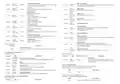
1. Product Data
Zigbee Heating Thermostat SR-ZG9092A
Radio Frequency
Input Voltage
2.4GHz
EU: AC200-240V, 50/60Hz
EU: AC200-240V
3680W @ 230V (resistive load)
16A
Output Voltage
Max Load
Important: Read All Instructions Prior to Installation
Function introduction
Max Current
Power Consumption
Ambient Temperature
Set Temperature Range
Hysteresis
<2W
0°C to 40°C (during operation)
0°C to 40°C
0.5°C to 2°C (default 0.5°C)
Home Interface
1. NTC/10K B(25/50℃)=3950 (default)
2. NTC/15K B(25/50℃)=3950
3. NTC/50K B(25/50℃)=3950
4. NTC/100K B(25/50℃)=3950
5. NTC/12K B(25/50℃)=3950
LED Display
Floor sensor type
Control Mode
TIME/SHIFT button, to set
time schedule of the
device quickly and move
the cursor
Function button, to
confirm, save setting
OFF, HEAT, ENERGY HEAT, AWAY, DRY
Move up and move down
buttons
F
Control type means which temperature sensor the device refers to
when it adjust temperature.
Mode button, to switch
operation modes and quit
Room sensor: adjust temperature refers to room temperature
(factory default type).
Control Type
Floor sensor: adjust temperature refers to floor temperature.
Room+Floor sensor: adjust temperature refers to both room
temperature and floor temperature.
Front side
Current ≤ 13A - 1.5mm² wire
Current > 13A to 16A - 2.5mm² wire
Wiring Requirement
IP Rating
IP21
80 mm
59 mm
10 mm 10 mm
31 mm
Control Pollution Degree (Method D)
Rated Impulse Voltage (Method D)
Relative Humidity
pollution degree 2
4kV
8% to 80%
80x80x52mm
Dimensions
CE,
LVD: EN 60730-1:2016;A1, EN IEC 60730-2-9:2019;A1
EMC & RF: EN IEC 61000-3-2:2019, EN 61000-3-3:2013+A1:2019,
EN 60730-1:2016+A1:2019, EN 60730-2-
19:2019+A1:2019+A2:2020, EN 50663:2017;ETSI EN 301 489-
1V2.2.3, ETSI EN301 489-3V2.1.1
SR-ZG9092A
Approvals
NTC
ETSI EN300 220-1 v3.1.1., ETSI EN300 220-2 V3.2.1
RED certificate: 2014/53/EU
L
L
N
N
• The Zigbee HVAC controller is a wireless thermostat for heating system, which complies to Zigbee 3.0
wireless protocol standards. The thermostat has 4 operation modes which can be controlled manually and
locally or through remote controlled through Zigbee gateway controller.
• All setup is performed via supported IEEE 802.15.4-based control platforms and other Zigbee3.0 compatible
control systems. Appropriate gateway control software allows for adjustment of control mode, control type,
schedule etc.
Floor temp sensor
AC Power input
Output
• Sensors: Air temperature
• THERMOSTAT MODE: OFF, HEAT, ENERGY HEAT, AWAY, DRY
• Measurement range: –10°C to +60°C
Back side
• Accuracy: ±0.1°C
• WARNING: Electrical power must be switched off during installation

| General | Details |
|---|---|
| Name | SUNRICHER SR-ZG9092A Zigbee Heating Thermostat Installation Guide |
| Make | SUNRICHER |
| Language | English |
| Filetype | PDF (Download) |
| File size | 0.88 MB |


SUNRICHER SR-ZG9092A Zigbee Heating Thermostat Installation Guide Overview
Summary of Contents
- Page 1: Product data Zigbee heating thermostat SR-ZG9092A Input voltage: EU: AC200-240V, 50/60Hz Max load: 3680W @ 230V (resistive load) Important: Read all instructions prior to installation Set temperature range: 0°C to 40°C Control type means which temperature sensor the device refers to when it adjusts temperature. Wiring requirement: Current ≤ 13A - 1.5mm² wire; Current > 13A to 16A - 2.5mm² wire IP rating: IP21 The Zigbee HVAC controller is a wireless thermostat for heating systems, which complies with Zigbee 3.0 wireless protocol standards. All setup is performed via supported IEEE 802.15.4-based control platforms and other Zigbee 3.0 compatible control systems.
- Page 2: Home interface Away mode allows users to maintain indoor temperatures when no one is home, with a recommended setting of 4-10 degrees. Drying mode adjusts heating based on the set temperature within a short period. System setting interface allows users to set and view room and floor temperatures. Users can enter the system setting interface by pressing and holding the move up and down buttons for over 5 seconds. Auto mode schedule enables users to set specific temperature schedules for different times and days. Safety warnings include not installing the device with power applied and avoiding moisture exposure. Switch operation modes can be done from the home interface, displaying various modes for selection. Manual mode controls heating based on the current set temperature. Automatic mode follows a configured time schedule without allowing temperature modifications. The device enters a standby interface after 2 minutes of inactivity, with the display turning off after 1 minute.
- Page 3: Over heat alarm function can be disabled through the device or configured via the Thermostat Cluster. User can set time to leave home and time to go home according to their requirements. Hysteresis prevents the undulation of sensor temperature, allowing the controller to operate more efficiently. The device will execute Away Mode Temperature Schedule before the end time if away mode is activated. Dry mode can be set to quickly heat and dry the floor, with configurable duration. Window open detect function disables the relay to save energy when the temperature drops below a certain threshold. Monitor set function allows real-time monitoring of over current, over heat, and freezing. The device can acquire local time from a bound device under specific conditions. Max current setting can disable the over current alarm function directly or through configuration. Room temperature alarm will force the relay to turn off if the temperature exceeds the set value.
- Page 4: Floor sensor (NTC 10K by default) If external sensor is broken, the user can buy NTC sensor by themselves. This brightness can also be configured through the proprietary attribute OperateDisplayLcdBrightness. Display auto off (60S by factory setting). Child lock can be enabled by pressing and holding both buttons for over 10S. Internal over heat protection ensures the safety of the device. Control type means which temperature sensor the device refers to when it adjusts temperature. Temp compensation is necessary to account for tolerance caused by the sensor or other factors. Factory resetting will remove the device from Zigbee network and restore all parameters to factory default. Display temp type defines which sensor temperature will be displayed on the Home page.
- Page 5: The value of attribute Occupancy (0x0002) of Thermostat (0x0201) is 0, indicating that Away Mode is activated. If the gateway sends a command to modify the attribute SystemMode (0x001c) of Thermostat (0x0201), the thermostat will quit Away Mode. The proprietary attribute 0x2002 (Manufacturer Code=0x1224) of the cluster 0x0201 can be modified to configure whether it is in away mode or at home. Away Mode uses the attribute UnOccupiedHeatingSetpoint to set temperature, while other modes use the attribute OccupiedHeatingSetpoint. The thermostat provides three Zigbee application endpoints. Application Endpoint #0 is the ZigBee Device Object (ZDO) with standard management features. Application Endpoint #1 is designated for the Thermostat with a generic device type. The device allows a factory reset of attributes without leaving the network. The Reset to Factory Defaults command resets all attributes of all clusters to their factory defaults. The Scenes command allows storing one or more scenes per group, where each scene consists of a pre-set on/off state value.
- Page 6: reportable outdoor temperature is the floor temperature with a maximum resolution of 0.01 ºC. If true, the scene identified by CurrentGroup and CurrentScene is currently active. When the occupancy flag is set to 1, it indicates the space is occupied. Room temperature calibration range is -30 to 30, with a maximum resolution of 0.1°C. Adds a scene with or without a scene field set. Returns the scene field set, name, and transition times for a scene. Removes a scene from the scene table. Stores the device’s current state as a scene or updates a previously stored scene. Indicates the relay on/off status, supporting only the heat state. The mode after reset power of the device can be set to default mode or last status before power off.
- Page 7: Floor sensor calibration involves temperature compensation for the external sensor, with a range of -30 to 30°C and a default value of 0. The duration of Dry Mode ranges from 5 to 100 minutes, with a default value of 5. The mode after Dry Mode can be OFF, Manual mode, Auto mode (default), or Away mode. The threshold to detect an open window ranges from 0.3 to 8. Hysteresis setting ranges from 5 to 20, with a default value of 5. Room temperature alarm threshold ranges from 0.20 to 60°C, with a default value of 45. The real displayed voltage is calculated using RMSVoltage, ACVoltageMultiplier, and ACVoltageDivisor. The alarm server can generate commands related to electrical measurement. The unit of metering data is always kWh. The alarm code for electrical measurement is 0.
- Page 8: Insert the power and heater wires to the correct device terminals by inserting a small Phillips-head screwdriver in the slot beneath each terminal to open. The Time cluster is a general cluster for time based on a UTC time in seconds since 1st January 2000. Power wires: connect Line & Neutral wires to L & N terminals labeled “IN”. Heater wires: connect Line & Neutral wires to L & N terminals labeled with “heating element” graphic. WARNING: The wire size shall be in compliance with regulations, using wire with insufficient size for big load will cause severe temperature rising. If the device has bound TIME cluster, then the device will acquire the value of Local Time (0x0007) spontaneously. Occupancy attribute specifies the sensed occupancy as follows: 1 = occupied, 0 = unoccupied. Pull-oriented firmware upgrade allows the server to control all stages of the upgrade process. This device should be installed by a licensed electrician in a manner that conforms to local regulations and building codes. WARNING: Electrical power must be switched off during installation.

EPH CONTROLS RDT Recessed Room Thermostat Installation Guide

NT NetX X5N-SM Thermostat Installation Guide

Wengart TP808 Wi-Fi Low Voltage Thermostat User Guide

DEVIreg 130 Electronic Thermostat Installation Guide

SUNSKY BAC-2005 Smart Thermostat User Manual

EcoNet UETST800SYS Smart Thermostat User Guide

Danfoss CF Wireless Floorheating Controller and Room Thermostat Instruction Manual

NEOMITIS RTE0RFA Wireless Digital Room Thermostat and Receiver Instruction Manual

IHAVC CONTROLS T-32-P Universal Thermostat Instruction Manual

TROLEX TX2010 Surface Thermostat Instruction Manual