STELPRO UT202NP Series Non-Programmable Electric Thermostat Owner’s Manual


OWNER'S MANUAL
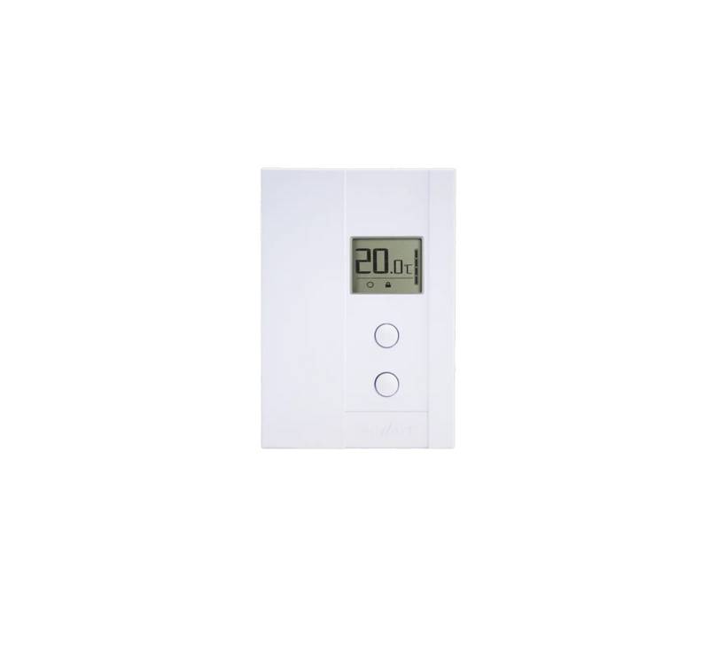
UT202NP NON PROGRAMMABLE
ELECTRONIC THERMOSTAT
THANK YOU FOR YOUR PURCHASE!
QUESTION? PROBLEM? CONTACT STELPRO CUSTOMER SERVICE.
E
WWW.UNIWATT.CA
1-844-STELPRO
ATT is a line of products manufactured by Stelpro. For more information

| General | Details |
|---|---|
| Name | STELPRO UT202NP Series Non-Programmable Electric Thermostat Owner’s Manual |
| Make | StelPro |
| Language | English |
| Filetype | PDF (Download) |
| File size | 0.25 MB |


STELPRO STF362NP Floor Heating Thermostat Owner’s Manual

STELPRO ST302P Programmable Electronic Thermostat Owner’s Manual

STELPRO SAT402ZB Smart Thermostat User Guide

STELPRO ST252NPFF Non-Programmable Electronic Thermostat Owner’s Manual

STELPRO ST402PFF Programmable Electronic Thermostat Owner’s Manual

STELPRO ASMC402 Maestro Zigbee Smart Programmable Thermostat User Guide

STELPRO SIBTE12C Electronic Thermostat Owner’s Manual

STELPRO STZW402+ Electronic Thermostat for The Smart Home Owner’s Manual

STELPRO SIBTE13F Electronic Thermostat User Guide

STELPRO STCP MULTIPLE PROGRAMMING ELECTRONIC THERMOSTAT User Guide
STELPRO UT202NP Series Non-Programmable Electric Thermostat Owner’s Manual Overview
Summary of Contents
- Page 1: Owner's manual for UT202NP series. UT202NP non programmable electronic thermostat. Thank you for your purchase! For questions or problems, contact Stelpro customer service. Unawat is a line of products manufactured by Stelpro. For more information, please contact customer service.
- Page 2: Warning Before installing and operating this product, the owner and/or installer must read, understand and follow these instructions and keep them handy for future reference. If these instructions are not followed, the warranty will be considered null and void. The following instructions must be adhered to in order to avoid personal injuries or property damages. All electric connections must be made by a qualified electrician, according to the electric and building codes effective in your region. Do not connect this product to a supply source other than 120 VAC to 240 VAC. You must regularly clean dirt accumulations on the thermostat. Do not use fluid to clean thermostat air vent. Do not install thermostat in a wet place. When a part of the product specification must be changed to improve operability or other functions, priority is given to the product specification itself. The actual product and packaging, as well as the name and illustration, may differ from the manual.
- Page 3: Description The UT202NP electronic thermostat can be used to control electric baseboards or convectors. It keeps the temperature of a room at the requested set point with a high degree of accuracy. This product is designed for installations with electrical current ranging from 1.25 A to 8.3 A (120-240 VAC). It possesses a user-friendly interface. This thermostat is not compatible with electrical current higher than 8.3 A with a resistive load. This thermostat is not compatible with electrical current lower than 1.25 A with a resistive load. This thermostat is not compatible with fan heaters. This thermostat is not compatible with central heating systems. Parts supplied include one thermostat with a door on the front, two mounting screws, and two twist-on wire connectors suitable for copper wires.
- Page 4: Installation Selection of the thermostat location The thermostat must be mounted to a connection box on a wall facing the heating unit, at around 1.5 m (5 feet) above the floor level, on a section of the wall exempt from pipes or air ducts. Do not install the thermostat in a location where temperature measurements could be altered. Avoid locations close to a window, on an external wall, or close to a door leading outside. Do not expose the thermostat directly to the light or heat of the sun, a lamp, a fireplace, or any other heat source. Avoid locations close or in front of an air outlet, concealed ducts, or a chimney. Do not install in a location with poor air flow or frequent air drafts. Thermostat mounting and connection Cut off power supply on lead wires at the electrical panel to avoid any risk of electric shock. Ensure that the air vents of the thermostat are clean and clear of any obstruction.
- Page 5: Make the electrical connections using the supplied twist-on wire connectors. When making the connection with aluminum wire, make sure that you are using connectors identified CO/ALR. The thermostat wires do not have polarity. Therefore, the way they are connected is not important. 2-wire installation 4-wire installation
- Page 6: Open the door with your hand or by using a flat screwdriver. With hand: open by freeing the door at the top right corner of the thermostat. Using a flat screwdriver: insert the screwdriver in the side slot at the top right corner of the thermostat and turn delicately until the door is freed. Place all the wires inside the electrical box. Fix the thermostat to the electrical box using the two screws provided. Close the thermostat door. Turn on the power.
- Page 7: Operation Ambient temperature Set point Heating power indicator Pictograms Frost-free warning Comfort mode Security mode Temperature set points To adjust the set point, press the top button to increase or the bottom button to decrease the value.
- Page 8: The thermostat can display the ambient temperature and the set point in degrees Celsius or Fahrenheit. To switch from degrees Celsius to degrees Fahrenheit and vice versa, simultaneously press down the two buttons for 3 seconds. Once the three seconds are over, the °C or °F symbol will flash. Press down the top button to switch from degrees Celsius to degrees Fahrenheit, and conversely. The heating power used is displayed as a percentage indicated by the number of bars in the thermometer displayed. 4 bars = 75% to 100%, 3 bars = 50% to 75%, 2 bars = 25% to 50%, 1 bar = 1% to 25%, 0 bar = no heat. The Snowflake icon is displayed when the temperature set point is between 3°C (37°F) and 5°C (41°F). A minimum temperature will be maintained to ensure frost control.
- Page 9: Security mode allows for a maximum temperature set point that cannot be exceeded. To activate the security mode, adjust the set point to the desired maximum temperature and press both buttons for more than 13 seconds. The thermostat will lock once the icon appears. To deactivate the security mode, cut off the thermostat power for at least 20 seconds. After restoring power, press both buttons for 13 seconds to deactivate the security mode. The thermostat saves parameters in non-volatile memory to recover settings after power failures. Saved parameters include the set point, state of the security mode, and temperature unit. The security mode reactivates automatically if it was previously activated after a power failure. The icon will blink for 5 minutes after power restoration, allowing for deactivation. If not deactivated within 5 minutes, the security mode remains activated.
- Page 10: Troubleshooting In normal operating conditions, the thermostat housing may become hot to the touch. That is normal and will not affect the effective operation of the thermostat. Check if the thermostat is properly connected. Refer to the installation section. Heating is always on. Heating does not run even if the thermostat indicates it is on. The display does not turn on. Check the power supply at the electrical panel. The thermal protection of the heating unit has opened due to overheating. The display turns off a few minutes and then turns on again. The displayed ambient temperature is incorrect. If you are unable to solve the problem after having verified these points, please communicate with customer service.
- Page 11: Technical specifications Product code: UT202NP Supply voltage: 120-240 V Load at 120 V: 150-1000 watts Load at 240 V: 300-2000 watts Load control type: Resistive Frequency: 60 Hz Storage temperature: -40°C to 50°C (-40°F to 122°F) Operating temperature: -20°C to 50°C (-4°F to 122°F) Humidity: 5% to 98% without condensation Rated impulse voltage: Category II (1500 V)
- Page 12: This unit has a 2-year warranty. If at any time during this period the unit becomes defective, it must be returned to its place of purchase with the invoice copy. In order for the warranty to be valid, the unit must have been installed and used according to instructions. If the installer or the user modifies the unit, he will be held responsible for any damage resulting from this modification. The warranty is limited to the factory repair or the replacement of the unit. The warranty does not cover the cost of disconnection, transport, and installation.

Danfoss DEVIreg 530 Electronic Thermostat Installation Guide

sensi 1F76U-22WFB Series Lite Smart Thermostat Installation Guide

KETOTEK KTF0163 Series Smart Thermostat Instruction Manual

MYSAIR MS20 Thermostat User Manual

EUROLAMP HY08BW Digital Heating Smart Thermostat User Manual

Honeywell T4M Programmable Modulating Thermostat Installation Guide

GENERAL LIFE HT220 Wired Room Thermostat User Manual

hansgrohe AXOR CARLTON Thermostat Mixer Instruction Manual

Danfoss INT69 Thermal Protection Thermostat Instruction Manual

QUIETWarmth Type UCG Thermostat User Manual