STELPRO SAT402ZB Smart Thermostat User Guide


USER GUIDE
SAT402ZB | Smart thermostat
INS-SAT402ZB-EN-0421

| General | Details |
|---|---|
| Name | STELPRO SAT402ZB Smart Thermostat User Guide |
| Make | StelPro |
| Language | English |
| Filetype | PDF (Download) |
| File size | 2.31 MB |
 (1 votes, average: 5.00 out of 5)

STELPRO STF362NP Floor Heating Thermostat Owner’s Manual

STELPRO ST302P Programmable Electronic Thermostat Owner’s Manual

STELPRO ST252NPFF Non-Programmable Electronic Thermostat Owner’s Manual

STELPRO ST402PFF Programmable Electronic Thermostat Owner’s Manual

STELPRO ASMC402 Maestro Zigbee Smart Programmable Thermostat User Guide

STELPRO SIBTE12C Electronic Thermostat Owner’s Manual

STELPRO STZW402+ Electronic Thermostat for The Smart Home Owner’s Manual

STELPRO SIBTE13F Electronic Thermostat User Guide

STELPRO STCP MULTIPLE PROGRAMMING ELECTRONIC THERMOSTAT User Guide

STELPRO STCP Floor Heating Thermostat Multiple Programming User Guide
STELPRO SAT402ZB Smart Thermostat User Guide Overview
Summary of Contents
- Page 1: User guide for the SAT402ZB smart thermostat. Document version INS-SAT402ZB-EN-0421.
- Page 2: The 360° comfort experience. Congratulations! You’ve entrusted your home’s heating to the Allia smart thermostat. Your family’s comfort is in your hands. The Allia smart thermostat will help you reduce your electricity bill and ecological footprint. Create your own home ecosystem with the Allia mobile app. Designed and developed for Canada. Stelpro understands the special needs of our climate. By choosing Stelpro’s Allia, you are encouraging local innovation. The development of energy-efficient products contributes to a better future.
- Page 3: Compatibility What’s in the box and required tools Warning Before you get started Temperature display unit Heating mode Where to set up your hub Where to install your thermostats Installation Troubleshooting
- Page 4: Compatibility warning: This thermostat is not compatible with electric baseboards, inductive load systems, central heating systems, and resistive load systems with specific wattage and voltage limits. See page 21 for the Allia thermostat’s detailed technical specifications. What's in the box includes connection caps, mounting screws, and the Allia thermostat. You will need a #2 Phillips screwdriver to install the thermostat.
- Page 5: WARNING Before you get started, take a few minutes to read this guide and watch the Allia thermostat’s step-by-step installation video to ensure a safe and easy installation. Before installing or using the thermostat, the homeowner and installer must read and understand these instructions and keep them for future reference. The manufacturer will assume no responsibility and the warranty will be void if the installer or user does not follow them. Electrical connections must be made by a qualified electrician in accordance with the electrical and building codes in effect in your area. Connect the thermostat ONLY to a 120 VAC to 240 VAC power source and respect the load limits. Protect the heating system with appropriate circuit breakers or fuses. Clean the thermostat regularly to remove accumulated dirt. DO NOT use liquid to clean the ventilation openings of the thermostat. DO NOT install the thermostat in a place where it could get wet or on an exterior wall. To avoid any risk of overheating, leave a clearance of at least 30 cm (12 in.) around the thermostat so that it is adequately ventilated. WARNING: High voltage. Switch off the power before installation and maintenance.
- Page 6: Before you get started Where to set up your hub You can optimize the Allia mesh network with a minimum amount of planning. The hub allows you to manage the Allia thermostats and other Allia-compatible connected objects. Install the hub in the most central location possible to boost communication between various rooms. The more Allia-compatible connected objects you have, the more they will act as Zigbee signal repeaters.
- Page 7: Where to install your thermostats Install an Allia thermostat in every room where you want to control the temperature. Install the thermostat about 1.5 m (5 ft) above the floor, on an inside wall facing the heating system. The space in front of the thermostat must be completely clear for it to operate optimally. To avoid overheating, leave at least 30 cm (12 in.) clearance around the thermostat to ensure adequate ventilation. To avoid inaccurate temperature readings, do not install the thermostat near a window or door that leads outdoors. Do not install the thermostat in a place exposed to direct light or heat from the sun, a lamp, a fireplace, or any other heat source. Avoid placing the thermostat near an air vent. Do not install the thermostat near pipes, concealed ducts, or a chimney. Avoid placing the thermostat in a place with poor air circulation, such as behind a door. Do not install the thermostat in an area with a high dust concentration or where there are frequent drafts.
- Page 8: Installation Warning: The thermostat must be installed by a certified electrician. Turning the power off To protect yourself against electric shock, switch off the power to the wires at the electrical panel. Make sure the wires are no longer powered. Attaching the mounting plate Loosen the screw at the base of the thermostat until the thermostat and the mounting plate are no longer attached. Using the mounting screws provided, attach the thermostat mounting plate to the electrical box. Pass the power supply wires through the large opening in the center of the mounting plate. You can place the mounting plate to the left, center, or right of the electrical box according to your needs. Make sure that the mounting plate is straight so that the thermostat is also straight.
- Page 9: Connecting the electrical wires involves using the supplied connection caps to connect the Allia thermostat wires to the heating system and power supply wires according to the connection diagram. It is important to tighten the caps on the wires to ensure a secure connection. All wires should be placed in the electrical box after connection. The direction of the connection is crucial as the thermostat wires are polar. Improperly connected electrical wires pose a fire hazard. If the power supply wires are made of aluminum, CO/ALR connection caps should be used instead.
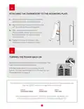
- Page 10: Attaching the thermostat to the mounting plate involves ensuring the ventilation openings are clean and unobstructed. Align the notch at the top of the thermostat with the notch on the mounting plate. Place the thermostat on the mounting plate carefully to avoid pinching the wires. Tighten the screw at the base of the thermostat to secure it in place. Restoring power to the heating system and thermostat is necessary to ensure the thermostat turns on. If it does not turn on, pressing one of its buttons should activate it. If the thermostat still does not turn on, refer to the troubleshooting section. The thermostat will display three preferences that need to be configured before use.
- Page 11: Thermostat interface provides 360° comfort at your fingertips. The interface includes adjustment buttons to set the temperature. The central button allows access to advanced menus and confirms selections. Icons indicate various statuses such as Zigbee connection established and heating mode. A locked keypad indicates restricted access. Flashing icons may signal low setpoint temperature or open window detection. Heating intensity is also displayed through the interface. An advanced menu indicator shows when additional options are available. A warning icon indicates the device has overheated.
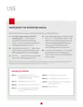
- Page 12: Navigating the advanced menus involves several steps to access options. From the home screen, press the central button for three seconds to access the advanced menus. The first menu that appears is the Zigbee connection menu. After selecting an option, press the central button to confirm the selection. The current value will flash, indicating it can be changed. Press the central button for three seconds to exit the advanced menus and return to the home screen. After 30 seconds of inactivity, the selected option will automatically be saved. Menu 10 includes Zigbee connection settings. Menu 20 allows for temperature format selection. Menu 40 includes keypad lock/unlock options.
- Page 13: Navigating the technical menus can be done from the home screen by pressing the central button for ten seconds. After three seconds, the advanced menus will be displayed. The technical menus include various options such as menu T1, T2, T3, thermostat version, and Zigbee version. The default setpoint temperature is set to 21°C (70°F). To change the setpoint temperature, use the buttons on the home screen. The increase button raises the setpoint temperature by 0.5°C (1°F) at a time. The decrease button lowers the setpoint temperature by 0.5°C (1°F) at a time. The heating system's operating intensity is indicated by an icon when the thermostat activates. The thermostat keypad must be unlocked for adjustments to be made. If part of the Allia ecosystem, the temperature will adjust automatically based on scenes or programs.
- Page 14: Connection to the Allia hub is essential for creating your Allia network. Install all thermostats before connecting them to the hub. Connect the thermostat closest to the Allia hub first, then progressively connect others. Additional Allia-compatible thermostats may be needed to boost the Zigbee signal. The hub must be connected to a Wi-Fi network to use the Allia app for connection. Once connected, an icon will appear on the thermostat's home screen. The Allia app will indicate successful connection of the thermostat. You can rename each thermostat for easier recognition. Select automatic connection on the thermostat to initiate the pairing process. The Zigbee channel will be displayed once the connection is established.
- Page 15: Connecting via the Allia hub allows for establishing a Zigbee connection. The Zigbee channel will be displayed when the connection is established. Press the button on the hub; the indicator light will turn blue and flash slowly. On the thermostat, go to menu 10 and select automatic connection (ON). The connection process is complete after repeating the procedure for each thermostat. If you do not have an Allia hub, you can connect the thermostat to an existing Zigbee network. You will not be able to use the Allia application or benefit from the Allia system’s features. The icon will flash quickly while the thermostat searches for the channel. Once connected to the Zigbee network, the icon will be displayed on the home screen. Press the central button to confirm the selection.
- Page 16: Setup involves setting three basic preferences when starting the thermostat for the first time. Temperature format can be displayed in degrees Celsius or degrees Fahrenheit. To change the temperature display unit, go to menu 20 and select °C or °F. Heating mode corresponds to the type of heating system controlled by the thermostat. To select the heating mode, go to menu 30 and choose between baseboard/convector mode or fan heater mode. Press the central button to confirm the selection for both temperature display and heating mode. Lobby mode options are available if the heating mode is set to fan heater. Zigbee connection setup is necessary for connecting the thermostat to an Allia hub. Install all thermostats before connecting them to the hub. When fan heater mode is selected, an icon is displayed on the thermostat’s home screen.
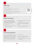
- Page 17: Lobby mode can only be selected if the heating mode is set to fan heater and open window detection is disabled. You can lock the thermostat keypad to prevent the setpoint temperature from being changed by mistake. When the keypad is locked, the icon is displayed on the thermostat’s home screen. You can change a thermostat’s setpoint temperature via the Allia app even when its keypad is locked. The thermostat can detect if a window is open in the room where it is located. The thermostat will then automatically adjust the setpoint temperature to 7°C (45°F) to avoid heating the room unnecessarily. This option is only available if Lobby mode is set to Standard.
- Page 18: Backlighting By default, the thermostat screen lights up when you touch one of the buttons. You can deactivate this function or adjust the intensity of the backlighting. Thermostat reset You can reset the thermostat to its default settings. The thermostat will reset. This process may take a few seconds. Warning: All settings will revert to their default values and the connection to the Zigbee network and hub will be deleted.
- Page 19: Troubleshooting Common problems The following table lists the most common problems and alerts you may encounter with your thermostat. The heating system is overheating. Inspect your heating system and replace it if it is defective. The thermostat has detected that a window is open. Close the window or deactivate the open window detection. There is an issue with the thermostat's Zigbee network. Reset the thermostat and reconnect it to the hub. Room temperature is below 0°C (32°F). Heating will remain active until the temperature reaches the setpoint temperature. Room temperature is above 50°C (122°F). Heating will remain inactive. The thermostat cannot measure the temperature (defective temperature sensor). Replace the thermostat. This alert may also be displayed temporarily immediately after a reset. It should disappear automatically after about 10 seconds.
- Page 20: Problem Solution The thermostat housing can become warm to the touch without affecting its efficiency or operation. The heating system operates continuously even after reaching the setpoint temperature. Ensure the thermostat wires are properly connected. The heating is not operational despite the thermostat indicating otherwise. The thermostat does not switch on after installation. Check that the circuit breaker for the heating system is set to OFF and that any switches are ON. The thermostat does not display the correct room temperature. Ensure there are no drafts or heat sources near the thermostat. The thermostat’s buttons do not respond, except for advanced menu access. The thermostat may be too far from another thermostat in the network.
- Page 21: Technical specifications Default values Temperature display Setpoint temperature Zigbee connection Heating mode Actual measured temperature Storage conditions and use Electrical characteristics Connectivity
- Page 22: Warranty This device is guaranteed for three years. If it stops working properly during this period, please return it to the place you purchased it with a copy of your invoice. For this warranty to be valid, the device must be installed and used according to the guidelines outlined in this guide. If the installer or user modifies the device in any way, they will be held responsible for any damage resulting from this modification. The warranty is limited to factory repair or replacement of the unit. It does not cover disconnection, transportation, and installation costs. Need help? Contact customer service.

ESi ESRTP6C, ESRTP6CW Centro Prog Room Thermostat User Guide

EZAIoT 20230324 IPS Colorful LCD Screen Touch Smart Thermostat User Manual

beok BOT-323W Room Thermostat Instruction Manual

Amana DS01 PTAC Wireless Thermostat User Manual

GREYSTONE TLGLF24X01 Glass Low Limit Thermostat Instruction Manual

GENERALLIFE ARUNA 302S RF Wireless Room Thermostat User Manual

GENERAL HT300S Smart Room Thermostat User Manual

REHAU NEA H 24 V Room Thermostat Instruction Manual

75F HyperStat All In one Commercial Thermostat User Manual

ELEKTROBOCK PT02 Electronic Pipe Thermostat Instruction Manual