Home > OJ Electronics > OJ ELECTRONICS MWD5-1999-R3C3 Voice Thermostat Instructions
OJ ELECTRONICS MWD5-1999-R3C3 Voice Thermostat Instructions


MWD5-1999-R3C3
INSTRUCTIONS
• English

| General | Details |
|---|---|
| Name | OJ ELECTRONICS MWD5-1999-R3C3 Voice Thermostat Instructions |
| Make | OJ Electronics |
| Language | English |
| Filetype | PDF (Download) |
| File size | 0.19 MB |


OJ ELECTRONICS UTN5 OJ Microline Non Programmable Thermostat User Manual

OJ ELECTRONICS UTN5 Non Programmable Touch Thermostat Instruction Manual

OJ ELECTRONICS MWD5-1999-UAC3 Voice Control Wi-Fi Thermostat Instructions

OJ ELECTRONICS UDG-4999 Thermostat with Class A GFCI Owner’s Manual

OJ ELECTRONICS MCD5 Touch Thermostat Instructions

OJ ELECTRONICS MCD3 Digital Thermostat Instructions

OJ ELECTRONICS UTN-4991 Non Programmable Thermostat Owner’s Manual

OJ ELECTRONICS MWD5-1999-R3C3 Voice Thermostat Instructions Overview
Summary of Contents
- Page 1: INSTRUCTIONS
- Page 2: INTRODUCTION
- Page 3: Page 3
- Page 4: Page 4
- Page 5: Page 5
- Page 6: Page 6
- Page 7: Introduction The thermostat is an electronic PWM/PI thermostat for temperature control by means of an NTC sensor located either externally or internally within the thermostat. The thermostat is for flush mounting in a wall socket. A baseplate for wall mounting is also available. This thermostat can be used as a controller for electric room heating pursuant to EN 50559. Important safety instructions To avoid electric shock, disconnect the heating system power supply at the main panel before carrying out any work on this thermostat and associated components. Installation must be carried out by qualified personnel in accordance with appropriate statutory regulations. Installation must comply with national and/or local electrical codes. This instruction must be observed, otherwise the liability of the manufacturer shall be voided. Any changes or modifications made to this thermostat shall void the liability of the manufacturer. Maximum product lifetime is achieved if the product is not turned off but set at the lowest possible set point/frost protection when heat is not required.
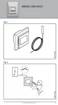
- Page 8: The language used in the original documentation is English. Other language versions are a translation of the original documentation. The manufacturer cannot be held liable for any errors in the documentation. The manufacturer reserves the right to make alterations without prior notice. Content may vary due to alternative software and/or configurations. The floor sensor contains a safety extra-low voltage (SELV) circuit. It is strongly recommended that the cable and sensor are placed in a non-conductive installation pipe embedded in the floor. The sensor cable must be led through a separate conduit or segregated from power cables. The floor sensor must be centred between loops of heating cable. The two-core cable must be placed in a separate pipe or segregated from power cables in some other way.
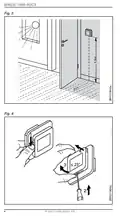
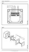
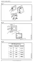
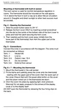
- Page 9: Mounting of thermostat with built-in sensor The room sensor is used for comfort temperature regulation in rooms. The thermostat should be mounted on the wall approx. 1.5 m above the floor in such a way as to allow free air circulation around it. Draughts and direct sunlight or other heat sources must be avoided. Slide the power button down to Off “0”. Release the front cover ONLY by inserting a small screwdriver into the slot at the centre of the bottom side of the front cover to press and hold the catch securing the front cover. Connect the wires in accordance with the diagram. The wires must be connected as follows: Neutral (N), Live (L), Output, max. 16 A. Mount the thermostat in the wall socket. Fit the frame and carefully press the cover onto the thermostat. Ensure that both the power slide button on the cover and the power switch pin in the thermostat are down. Warning! Do not apply pressure to the corners of the display cover or to the display itself. DO NOT open the thermostat by releasing the four fixing clips on the back.
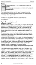
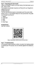
- Page 10: There is an ON/OFF switch on the left side of the thermostat: up is ON - down is OFF. The resistive touchscreen requires a soft tap with your fingertip to register the touch. The Installer Wizard on the touchscreen will guide you through the setup of region, language, date, time, and floor type. If the sensor is disconnected or short-circuited, the heating system is switched off. The sensor can be checked against the resistance table. See user manual for programming details.
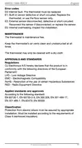
- Page 11: Error codes E0: Internal fault. The thermostat must be replaced. E1: Built-in sensor defective or short-circuited. Replace the thermostat, or use the floor sensor only. E2: External sensor disconnected, defective or short-circuited. Reconnect the sensor if disconnected, or replace the sensor. E5: Internal overheating. Inspect the installation. Maintenance The thermostat is maintenance free. Keep the thermostat’s air vents clean and unobstructed at all times. The thermostat may only be cleaned with a dry cloth. Approvals and standards OJ Electronics A/S hereby declares that the product is in conformity with the following directives of the European Parliament: LVD - Low Voltage Directive EMC - Electromagnetic Compatibility RoHS - Restriction of the use of certain Hazardous Substances RED - Radio Equipment Directive Protection from electric shock must be assured by appropriate installation. Must be installed according to the requirements of Class II (reinforced insulation).
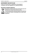
- Page 12: Environment and recycling Protect the environment by disposing of the package in compliance with local regulations for waste processing. Recycling of obsolete appliances Equipment containing electrical components must not be disposed of along with domestic waste. It must be separately collected together with electrical and electronic waste in accordance with current local regulations.
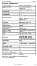
- Page 13: Technical specifications Purpose of control Electrical underfloor heating Wall mounting in a socket or mounting box Supply voltage: 100-240 VAC, 10% 50/60 Hz Max. pre-fuse: 16 A Enclosure rating: IP 21 Output relay: Make contact - SPST - NO, Max. 16 A / 3600 W Standby consumption: ≤0.5 W Battery life, typical: 5 years (storage)
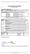
- Page 14: Declaration of conformity Identification of apparatus: OCD5-1999-xxSy OCD5-1999-xxPy OWD5-1999-xxPy MCD5-1999-xxSy MCD5-1999-xxPy MWD5-1999-xxPy The object of the declaration described above is in conformity with the relevant Union harmonization legislation. EMC Directive DIRECTIVE 2014/30/EU OF THE EUROPEAN PARLIAMENT AND OF THE COUNCIL Low Voltage Directive DIRECTIVE 2014/35/EU OF THE EUROPEAN PARLIAMENT AND OF THE COUNCIL RoHS Directive DIRECTIVE 2011/65/EU OF THE EUROPEAN PARLIAMENT AND OF THE COUNCIL RED Directive DIRECTIVE 2014/53/EU OF THE EUROPEAN PARLIAMENT AND OF THE COUNCIL Approval Manager: Palle Jensen of the signatory empowered to bind OJ ELECTRONICS A/S
- Page 15: Page 15

Honeywell RTH8500 Wifi Thermostat User Manual

Uponor ETN4 Ecoflex Supra Standard Thermostat Instruction Manual

Honeywell CMR707A1049 Programmable Room Thermostat User Guide

WATTS 563 WiFi Thermostat User Manual

King K901-B Wifi Programmable Thermostat Instruction Manual

COPELAND ST55 Sensi Smart Thermostat Instruction Manual

COMPUTHERM Q20 Programmable Digital Room Thermostat Instruction Manual

MODINE 5-580.4 Programmable Room Thermostat Installation Guide

UNDERFLOOR HEATING WORLD UM1 Thermostat Instruction Manual

GENERAL LIFE Senna 270S RF Wireless Room Thermostat User Manual