Home > OJ Electronics > OJ ELECTRONICS MCD5 Touch Thermostat Instructions

OJ ELECTRONICS MCD5 Touch Thermostat Instructions

MCD5-1999-ASP3  
INSTRUCTIONS  
• English  
• Svenska  
GeneralDetails
NameOJ ELECTRONICS MCD5 Touch Thermostat Instructions
MakeOJ Electronics
LanguageEnglish
FiletypePDF (Download)
File size0.19 MB
Download PDF
1 Star2 Stars3 Stars4 Stars5 Stars (1 votes, average: 5.00 out of 5)
Loading...
OJ ELECTRONICS UTN5 OJ Microline Non Programmable Thermostat User Manual
OJ ELECTRONICS UTN5 Non Programmable Touch Thermostat Instruction Manual
OJ ELECTRONICS UDG-4999 Thermostat with Class A GFCI Owner’s Manual
OJ ELECTRONICS MWD5-1999-UAC3 Voice Control Wi-Fi Thermostat Instructions
OJ ELECTRONICS MWD5-1999-R3C3 Voice Thermostat Instructions
OJ ELECTRONICS MCD3 Digital Thermostat Instructions
OJ ELECTRONICS UTN-4991 Non Programmable Thermostat Owner’s Manual

OJ ELECTRONICS MCD5 Touch Thermostat Instructions
Get the free PDF manual for the OJ ELECTRONICS MCD5 Touch Thermostat Instructions and access setup steps, usage instructions, and troubleshooting tips. 👉 View online or download now to keep your thermostat running smoothly!
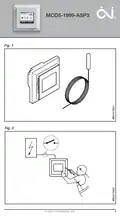
OJ ELECTRONICS MCD5 Touch Thermostat Instructions Overview

Summary of Contents

  • Page 1: INSTRUCTIONS
  • Page 2: Illustrations Instructions English Svenska
  • Page 3: Page 3
  • Page 4: Page 4
  • Page 5: Page 5
  • Page 6: Page 6
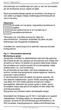
  • Page 7: Introduction The thermostat is an electronic PWM/PI thermostat for temperature control by means of an NTC sensor located either externally or internally within the thermostat. The thermostat is for flush mounting in a wall socket. A baseplate for wall mounting is also available. This thermostat can be used as a controller for electric room heating pursuant to EN 50559. Important safety instructions To avoid electric shock, disconnect the heating system power supply at the main panel before carrying out any work on this thermostat and associated components. Installation must be carried out by qualified personnel in accordance with appropriate statutory regulations. Installation must comply with national and/or local electrical codes. This instruction must be observed, otherwise the liability of the manufacturer shall be voided.
  • Page 8: Any changes or modifications made to this thermostat shall void the liability of the manufacturer. Maximum product lifetime is achieved if the product is not turned off but set at the lowest possible set point/frost protection when heat is not required. The language used in the original documentation is English. Other language versions are a translation of the original documentation. The manufacturer cannot be held liable for any errors in the documentation. The manufacturer reserves the right to make alterations without prior notice. Content may vary due to alternative software and/or configurations. The floor sensor contains a safety extra-low voltage (SELV) circuit, allowing it to be placed as close to the floor surface as possible. It is strongly recommended that the cable and sensor are placed in a non-conductive installation pipe embedded in the floor. The sensor cable must be led through a separate conduit or segregated from power cables.
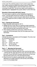
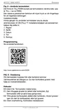
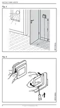
  • Page 9: Mounting of thermostat with built-in sensor The room sensor is used for comfort temperature regulation in rooms. The thermostat should be mounted on the wall approx. 1.5 m above the floor. Draughts and direct sunlight or other heat sources must be avoided. Connect the wires in accordance with the diagram. The wires must be connected as follows: Neutral (N), Live (L), Output, max. 16 A. Do not connect external floor sensor. Mount the thermostat in the wall socket. Ensure that both the power slide button on the cover and the power switch pin in the thermostat are down. Warning! Do not apply pressure to the corners of the display cover or to the display itself.
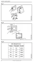
  • Page 10: Do not open the thermostat by releasing the four fixing clips on the back. There is an ON/OFF switch on the left side of the thermostat: up is ON - down is OFF. The resistive touchscreen requires a soft tap with your fingertip to register the touch. The Installer Wizard on the touchscreen will guide you through the setup of region, language, date, time, and floor type. See user manual for programming. If the sensor is disconnected or short-circuited, the heating system is switched off. The sensor can be checked against the resistance table.
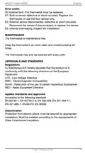
  • Page 11: Error codes E0: Internal fault. The thermostat must be replaced. E1: Built-in sensor defective or short-circuited. Replace the thermostat, or use the floor sensor only. E2: External sensor disconnected, defective or short-circuited. Reconnect the sensor if disconnected, or replace the sensor. E5: Internal overheating. Inspect the installation. Maintenance The thermostat is maintenance free. Keep the thermostat’s air vents clean and unobstructed at all times. The thermostat may only be cleaned with a dry cloth. Approvals and standards OJ Electronics A/S hereby declares that the product is in conformity with the following directives of the European Parliament: LVD - Low Voltage Directive EMC - Electromagnetic Compatibility RoHS - Restriction of the use of certain Hazardous Substances RED - Radio Equipment Directive Protection from electric shock must be assured by appropriate installation. Must be installed according to the requirements of Class II (reinforced insulation).
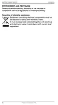
  • Page 12: Environment and recycling Protect the environment by disposing of the package in compliance with local regulations for waste processing. Recycling of obsolete appliances Equipment containing electrical components must not be disposed of along with domestic waste. It must be separately collected together with electrical and electronic waste in accordance with current local regulations.
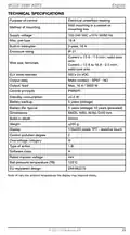
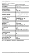
  • Page 13: Technical specifications Purpose of control: Electrical underfloor heating Wall mounting in a socket or mounting box Supply voltage: 100-240 VAC, 50/60 Hz Max. pre-fuse: 16 A Enclosure rating: IP 21 Output relay: SELV 24 VDC Control principle: PWM/PI Standby consumption: ≤0.5 W Dimensions: H/84, W/84, D/40 mm
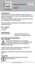
  • Page 14: Introduktion Termostaten är en elektronisk PWM/PI-termostat för temperaturstyrning med hjälp av en NTC-givare. Termostaten är avsedd för infälld montering i vägg. Det finns också en monteringsplåt för montering på vägg. Denna termostat kan användas för att styra eluppvärmning av rum enligt SS-EN 50559. Viktiga säkerhetsanvisningar För att undvika elektrisk stöt ska du koppla från strömkabeln till värmesystemet vid huvudpanelen innan du utför något arbete. Installation måste utföras av behörig personal i enlighet med gällande regelverk. Installationen måste efterleva nationella och/eller lokala elektriska koder. Denna instruktion måste följas. Annars upphör tillverkarens ansvar.
  • Page 15: Alla ändringar och modifieringar som görs av den här termostaten gör att tillverkarens ansvar upphör att gälla. Maximal produktlivslängd uppnås om produkten inte stängs av, utan ställs in på lägsta möjliga inställningspunkt/frostskydd när värme inte krävs. Det språk som används i originaldokumentationen är engelska. Tillverkaren kan inte hållas ansvarig för några fel i dokumentationen. Tillverkaren förbehåller sig rätten att göra förändringar utan föregående meddelande. Golvgivaren innehåller en säkerhetskrets med extra låg spänning. De två ledarna som ansluter givaren till monteringslådan måste isoleras extra, t.ex. med krympslang. Vi rekommenderar starkt att kabeln och givaren placeras i ett icke ledande installationsrör i golvet. Givarkabeln måste dras genom ett separat rör eller skiljas från strömförande kablar. Golvgivaren ska centreras mellan värmekabelns slingor.
  • Page 16: Montering av en termostat med inbyggd givare. Rumsgivaren används för att ge komfortabel värmereglering i rum. Termostaten bör monteras på väggen ca 1,5 m över golvet. Drag och direkt solinstrålning eller andra värmekällor ska undvikas. Anslut kablarna enligt ritningen. Kablarna ska anslutas på följande sätt: Nolledare (N), Fasledare (L). Montera termostaten i väggdosan. Kontrollera att både skjutbrytaren i locket och brytarstiftet i termostaten är nere. Öppna inte termostaten genom att lossa de fyra fästklämmorna på baksidan. Varning! Tryck inte på hörnen i teckenfönstrets ram eller på själva teckenfönstret.
  • Page 17: Det finns en TILL/FRÅN-brytare på termostatens vänstra sida. Den resistiva pekskärmen behöver ett mjukt tryck av din fingertopp för att registrera beröringen. Installationshjälp: Första gången du använder termostaten ska du skjuta strömbrytaren till ON [TILL]. Installationshjälpen på pekskärmen hjälper dig ställa in region, språk, datum, tid och golvtyp. Om termostaten kopplas från eller kortsluts kommer värmesystemet att stängas av. Felkoder: E0: Internt fel. Termostaten måste bytas. E1: Den inbyggda givaren är defekt eller kortsluten. Byt termostaten eller använd bara golvgivaren. E2: Yttre givare bortkopplad, defekt eller kortsluten. Anslut givaren igen om den är bortkopplad, eller byt givaren. E5: Intern överhettning. Kontrollera installationen. Se användarhandboken för programmering.
  • Page 18: Termostaten är underhållsfri. Håll alltid termostatens luftventiler rena och fria från hinder. Termostaten får bara rengöras med en torr trasa. OJ Electronics A/S meddelar härmed att produkten uppfyller kraven enligt följande direktiv från Europaparalamentet: LVD - Low Voltage Directive EMC - Electromagnetic Compatibility RoHS - Restriction of the use of certain Hazardous Substances RED - Radio Equipment Directive Skydd mot elektrisk stöt måste säkerställas genom rätt installation. Måste installeras enligt kraven för klass II (förstärkt isolering). Skydda miljön genom att göra dig av med förpackningen i enlighet med lokala föreskrifter för avfallshantering.
  • Page 19: Tekniska specifikationer Syfte med kontroll Elektrisk undergolvsvärme Väggmontering i ett uttag eller monteringsbox Strömförsörjning 100-240 VAC, 10% 50/60 Hz Maximal förspänning Inbyggt störningsskydd Infattningsklass IP 21 Ström ≤ 13 A - 1,5 mm², fast tvinnad kabel Ström > 13 A till 16 A - 2,5 mm², fast tvinnad kabel
  • Page 20: Page 20