
Home > GE Appliances > GE APPLIANCES RAK150VF2 Wall Thermostat Instruction Manual
GE APPLIANCES RAK150VF2 Wall Thermostat Instruction Manual












INSTALLATION INSTRUCTIONS
RAK150VF2
SAFETY INFORMATION....................2
OVERVIEW ........................................3
INSTALLATION................................ 4
WIRING DIAGRAMS ..........................8
CONFIGURATION MODE.................10
OPERATING FUNCTIONS............... 13
TROUBLESHOOTING.......................15
WARRANTY.....................................16
31-5000604 Rev. 1 02-22 GEA


| General | Details |
|---|---|
| Name | GE APPLIANCES RAK150VF2 Wall Thermostat Instruction Manual |
| Make | GE Appliances |
| Language | English |
| Filetype | PDF (Download) |
| File size | 0.22 MB |
 (1 votes, average: 5.00 out of 5)
 Loading...

GE APPLIANCES RAK160W2 Wireless Thermostat User Manual

GE APPLIANCES RAK190V Energy Management Thermostat Owner’s Manual

GE APPLIANCES RAK190V 2 Way Energy Management Thermostat Instruction Manual

GE APPLIANCES RAK150VF2 Digital Wall Thermostat Instruction Manual

GE APPLIANCES THERMOSTAT Owner’s Manual

GE APPLIANCES RAK150VF2 Wall Thermostat Instruction Manual Overview
Summary of Contents
- Page 1: Installation instructions Safety information Overview Installation Wiring diagrams Configuration mode Operating functions Troubleshooting Warranty
- Page 2: Important safety information should be read before using the thermostat. Always turn off power at the main power supply before installing, cleaning, or removing the thermostat to avoid electrical shock hazards. Do not use on voltages over 30 VAC, as higher voltages can damage the thermostat and pose shock or fire hazards. All wiring must conform to local and national electrical and building codes. Use the thermostat only as described in the manual. The electrical rating is 24 VAC (18–30 VAC) with a maximum of 1 amp per terminal and 4 amp maximum total load. The operating temperature range is 40°F–99°F (4°C–37°C) with a temperature set range of 60°F–85°F (15°C–29°C) and an accuracy of 1°F (0.5°C). System configurations include factory settings for 3-stage heat and 2-stage cool, as well as alternate settings for 2-stage heat and 1-stage cool. The terminations are R, C, B, Y1, W, Y2, GL, GH. The maximum wiring length is 66ft (20 meters) for AWG18 and 60ft (18 meters) for AWG20.
- Page 3: Introduction overview Thermostat controls Display Up/down buttons Mode Thermostat base layout Wiring Fan Mounting Reset
- Page 4: Installation instructions include a warning about electrical shock hazards, emphasizing the importance of turning off power before removing the existing thermostat. The package contents include a thermostat base, thermostat cover, wiring labels, screws, and wall anchors. Tools required for installation are a hammer, screwdriver, and putty.
- Page 5: Installation instructions provide a step-by-step guide for removing an existing thermostat. Turn off power to the heating and cooling system by removing the fuse or switching off the circuit breaker. Remove the cover of the old thermostat to expose the wires. Label the existing wires with the enclosed wire labels before removing them. After labeling, remove the wires from the wire terminals. Remove the existing thermostat base from the wall. Refer to the following section for instructions on how to install the new thermostat.
- Page 6: Installation instructions for the thermostat must conform to local and national building and electrical codes and ordinances. Mount the thermostat about five feet above the floor and avoid direct sunlight, outside walls, behind doors, or areas affected by vents or ducts. Turn off power to the heating and cooling system before installation. Remove the cover by inserting and twisting a coin or screwdriver in the slots on the top of the thermostat. Position the thermostat base against the wall and ensure wires will feed through the wire opening. Mark the placement of the mounting holes with the base level. Use a hammer to tap supplied anchors into the mounting holes. Align the thermostat base with the mounting holes and feed the control wires through the wire opening.
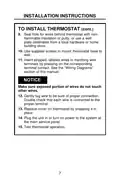
- Page 7: Installation instructions for the thermostat include sealing the hole for wires with non-flammable insulation or putty. Use supplied screws to mount the thermostat base to the wall. Insert stripped, labeled wires into matching wire terminals. Ensure exposed wires do not touch other wires. Gently tug the wire to confirm proper connection. Double-check that each wire is connected to the correct terminal. Replace the cover on the thermostat by snapping it in place. Plug the unit in or turn on power to the system at the main service panel. Test the thermostat operation.
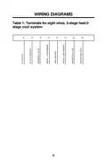
- Page 8: Wiring diagrams Terminals for eight wires. 3-stage heat/2-stage cool system. R C B Y1 W Y2 GL GH
- Page 9: Wiring diagrams provide essential information for different systems. Terminals for a seven-wire, 2-stage heat/1-stage cool system include R, C, B, Y1, W, Y2, GL, and GH. Terminals for a six-wire, 1-stage heat/1-stage cool system include R, C, B, Y1, W, Y2, GL, and GH.
- Page 10: Configuration mode is used to set the RAK150VF2 to match the heating/cooling system. The default setting is for 2-stage cooling with a 3-stage heat pump system. To configure the RAK150VF2, ensure the thermostat is in OFF mode and remove the front cover. Enter configuration mode by holding CONFIG for approximately 2 seconds. Press the change settings buttons to navigate through the screens. Hold the CONFIG button for approximately 2 seconds to save changes and exit the configuration menu. The setup screens for configuration mode include options for temperature scale (°F or °C) and temperature differential settings for stages 1 and 2. The default factory setting for temperature scale is Fahrenheit. The temperature differential for stage 1 can be set between 1–9°F (0.5-4.5°C) with a default setting of 1°F (0.5°C). The temperature differential for stage 2 can also be set between 1–9°F (0.5-4.5°C) with a default setting of 1°F (0.5°C).
- Page 11: Configuration mode Temperature differential—stage 3 (1–9°F) (.5-4.5°C) Set the number of degrees between when stage 2 turns on and stage 3 turns on. Default factory setting is 1°F/.5ºC. System - select appropriate cooling/heating system based on model selection. HP b2: two stage cooling / two stage heat pump with a backup 3rd stage of resistance heat. HP b1: single stage cooling / single stage heat pump with a backup 2nd stage of resistance heat. ELC: single stage cooling / single stage resistance heating. Default factory setting is HP b2. Minimum cool setpoint (60, 64, 66, 68, 70, 72, 74, 76°F) (15, 17, 19, 20, 21, 22, 23, 24°C).
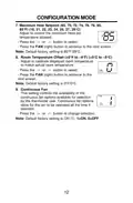
- Page 12: Configuration mode Maximum heat setpoint adjusts the maximum heat set temperature allowed. Press the or button to select. Press the FAN (right) button to advance to the next screen. Default factory setting is 85°F/29°C. Room temperature offset adjusts to calibrate displayed room temperature to match actual room temperature. Press the or button to select. Press the FAN (right) button to advance to the next screen. Default factory setting is 0°F/0°C. Continuous fan controls the availability of the continuous fan options. Default factory setting is ON (1).
- Page 13: Operating functions include Off, Heat, and Cool modes. In Off mode, the thermostat will not activate heating or cooling devices, but the manual fan can operate if Continuous Fan mode is enabled. Off mode is also used to access Configuration mode. In Heat mode, the thermostat controls the heating system, and users can set the desired temperature using the appropriate button. In Cool mode, the thermostat controls the cooling system, and users can also set the desired temperature with the button. Heating and cooling indicators are present to show the current mode of operation.
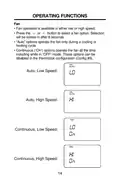
- Page 14: Fan operation is available in either low or high speed. Press the or button to select a fan option. Selection will be locked in after 8 seconds. “Auto” options operate the fan only during a cooling or heating cycle. Continuous (“On”) options operate the fan all the time including while in “OFF” mode. These options can be disabled in the thermostat configuration (Config #9). Auto, Low Speed: Auto, High Speed: Continuous, Low Speed: Continuous, High Speed:
- Page 15: Troubleshooting tips provide solutions for common problems. Check for 24 VAC if the display is blank. Verify that wiring is correct if the system fan does not come on properly. Ensure 24 VAC is present as all thermostat buttons will be inoperative without it. Adjust the temperature differential if the thermostat turns on and off too frequently. Check fan selection; if set to ON, the fan will run continuously. Verify that the wall hole is plugged to prevent airflow if room temperature is not correct. There is a 3-minute time delay for the compressor when changing function or setting. On some models, the fan may have a minimum run time/off time delay. Press the Reset button to reset the thermostat microprocessor for problems not listed above.
- Page 16: Thermostat warranty details are provided. Proof of the original purchase date is needed to validate the warranty. GE Appliances will replace the thermostat within one year from the date of original purchase if it fails due to a defect in materials or workmanship. Service trips to your location are not covered under the warranty. Improper installation is not covered; contact your installer for installation problems. You are responsible for providing adequate electrical connections to the product. The warranty does not cover failure resulting from modifications or unreasonable use. Labor necessary to move the unit in commercial locations is not covered. Incidental or consequential damage caused by defects with the thermostat is excluded. This warranty is extended to the original purchaser and any succeeding owner for products purchased for use within the USA and Canada.
- Page 17: Instructions d’installation Renseignements importants concernant la sécurité Vue d’ensemble Installation Schémas de câblage Configuration mode Fonctions d’utilisation Conseils de dépannage Garantie limitée
- Page 18: Renseignements importants concernant la sécurité. Lisez toutes les instructions avant d’utiliser cet appareil. Mettez toujours l’alimentation électrique hors tension avant d’installer, de nettoyer ou de retirer le thermostat. N’utilisez pas des tensions supérieures à 30 VAC. Tout le câblage doit être conforme aux Codes de l’électricité et du bâtiment locaux et nationaux. Utilisez ce thermostat aux seules fins décrites dans ce manuel. Caractéristiques électriques : 24 VAC (18–30 VAC), 1 ampère maximum par borne, 4 ampères maximum charge totale. Gamme des températures de fonctionnement : 40°F–99°F (4°C–37°C). Plage des réglages de température : 60°F–85°F (15°C–29°C). Configurations du système : Réglage à l’usine : Chauffage à deux étapes, refroidissement à une étape.
- Page 19: Présentation aperçu Commande du thermostat Écran Boutons fléchés Disposition de la base du thermostat Câblage Ventilateur Bouton de réinitialisation Bouton de configuration
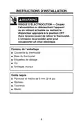
- Page 20: Instructions d'installation Risque d'électrocution — Coupez l'alimentation en débranchant l'appareil ou en retirant le fusible ou mettant le disjoncteur approprié à la position OFF avant de retirer le thermostat. Contenu de l'emballage Couvercle du thermostat Base du thermostat Vis Ancrages muraux Outils requis Perceuse et mèche de 5 mm Marteau Tournevis
- Page 21: Instructions d'installation Pour retirer le thermostat existant Mettez le système de chauffage et de climatisation hors tension en retirant le fusible ou en déclenchant le disjoncteur approprié. Retirez le couvercle du thermostat à changer. Ceci devrait exposer les fils. Étiquetez les fils existants à l’aide des étiquettes fournies avant d’enlever les fils. Après avoir étiqueté les fils, débranchez les fils des cosses. Retirez la base du thermostat existant du mur. Consultez la section suivante pour des instructions relatives à l’installation du thermostat.
- Page 22: Instructions d'installation Installation du thermostat L'installation de ce thermostat doit être conforme à tous les codes et tous les règlements des Codes du bâtiment et de l'électricité locaux et nationaux. Montez le thermostat à une hauteur d’environ 1,5 m (5 pi) au-dessus du plancher. Ne montez pas le thermostat sur un mur extérieur, directement exposé aux rayons de soleil, derrière une porte ou à un endroit où une bouche ou un conduit d’aération pourrait nuire au fonctionnement. Mettez le système de chauffage et de climatisation hors tension en retirant le fusible ou en déclenchant le disjoncteur approprié. Retirez le couvercle en insérant et tournant une pièce de monnaie ou un tournevis dans les fentes dans le haut du thermostat. Apposez la base du thermostat contre le mur où il doit être installé. Utilisez un niveau pour niveler et marquer l’emplacement des trous de montage. Utilisez une mèche de 5 mm (3/16 po) pour percer des avant-trous aux emplacements marqués pour les vis à bois. Alignez la base du thermostat sur les trous de montage et faites passer les fils de commande à travers le trou des fils.
- Page 23: Instructions d'installation Installation du thermostat Scellez le trou des fils derrière le thermostat à l’aide d’un isolant ou d’un mastic non inflammables. Utilisez les vis fournies pour monter la base du thermostat sur le mur. Insérez les fils dénudés et étiquetés dans les bornes correspondantes en pressant le contact des bornes. Assurez-vous que la partie exposée des fils ne touche pas aux autres fils. Tirez délicatement chaque fil pour vous assurer qu’il est bien raccordé. Assurez-vous que chaque fil est raccordé au conducteur électrique approprié. Replacez le couvercle sur le thermostat en l’enclenchant en place. Branchez l’unité ou mettez le système sous tension au niveau du panneau de service principal. Testez le fonctionnement du thermostat.
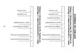
- Page 24: Chaud 24 VCA 24 V AC hot Neutre 24 VCA 24 V AC common Robinet inverseur Reversing valve Compresseur à 1 étape Chauffage électrique Compresseur à 2 étape Ventilateur intérieur bas
- Page 25: Chaud 24 VCA 24 V AC hot Neutre 24 VCA 24 V AC common Robinet inverseur Reversing valve Compresseur à 1 étape Chauffage électrique Ventilateur intérieur bas Ventilateur intérieur haut
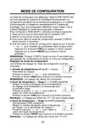
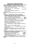
- Page 26: Mode de configuration Le mode de configuration est utilisé pour régler le RAK150VF2 afin qu’il corresponde au système de chauffage-refroidissement. La configuration par défaut de ce thermostat correspond à un système à thermopompe à 2 étapes de refroidissement et 3 étapes de chauffage. Pour configurer le RAK150VF2, exécutez les étapes suivantes : Assurez-vous que le thermostat est à la position OFF. Pour entrer dans le mode de configuration, pressez CONFIG durant environ 2 secondes. Une fois dans le mode de configuration, appuyez sur le bouton ou pour modifier les paramètres dans chaque écran. Les fenêtres de réglage du mode de configuration sont les suivantes : Échelle de températures (F ou C) — Choisir Fahrenheit ou Celsius. Écart de température — Étape 1 — (1–9°F) (.5-4.5°C) — Réglez le nombre de degrés entre la température du réglage et la température au démarrage pour la première étape. Écart de température — Étape 2 (1–9°F) (.5-4.5°C) thermopompe (HPb) seulement — Réglez le nombre de degrés entre le démarrage de l’étape 1 et le démarrage de l’étape 2.
- Page 27: Mode de configuration Écart de température — Étape 3 (1–9°F) (.5-4.5°C) Réglez le nombre de degrés entre le moment où l’étape 2 s’active et celui où l’étape 3 s’active. Le réglage par défaut est 1°F/.5ºC pour chaque étape. Système – Sélectionnez le système de chauffage-refroidissement approprié selon le modèle sélectionné. HP b2 : Thermopompe à refroidissement à 2 étapes et chauffage à 2 étapes avec chauffage d’appoint électrique de troisième étape. HP b1 : Thermopompe à refroidissement à 1 étape et chauffage à 1 étape avec chauffage d’appoint électrique de deuxième étape. ELC : Refroidissement à 1 étape et chauffage électrique à 1 étape. Le réglage par défaut est HP b2 pour chaque étape. Réglage de refroidissement minimal (60, 64, 66, 68, 70, 72, 74, 76°F) (15, 17, 19, 20, 21, 22, 23, 24°C). Le réglage par défaut est 60°F/15°C pour chaque étape.
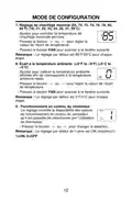
- Page 28: Mode de configuration Réglage de chauffage maximal (65, 70, 72, 74, 76, 78, 80, 85°F) (18, 21, 22, 23, 24, 26, 27, 29°C) Ajustez pour contrôler la température de chauffage maximale permise. Pressez le bouton ou pour régler la valeur de l’écart de température. Pressez le bouton FAN pour avancer à la fenêtre suivante. Remarque : Le réglage par défaut est 85°F/29°C pour chaque étape. Écart à la température ambiante (+9°F to –9°F) (+5°C to –5°C) Ajustez pour calibrer la température ambiante affichée afin de correspondre à la température ambiante réelle. Pressez le bouton ou pour régler la valeur de l’écart. Pressez le bouton FAN pour avancer à la fenêtre suivante. Remarque : Le réglage par défaut est 0°F/0°C pour chaque étape. Fonctionnement en continu du ventilateur FAN Ce réglage contrôle la disponibilité des options de fonctionnement en continu du ventilateur. Pressez le bouton ou pour changer la sélection. Remarque : Le réglage par défaut de l’usine est ON (marche)(1).
- Page 29: Fonctions d’utilisation OFF (arrêt) • Dans ce mode, le thermostat n’allumera pas les dispositifs de chauffage ou de refroidissement. • Le mode OFF sert aussi à accéder aux modes Configuration. Heat (chauffage) • Dans ce mode, le thermostat contrôle le système de chauffage. • Appuyez sur le bouton pour régler la température souhaitée. Cool (refroidissement) • Dans ce mode, le thermostat contrôle le système de refroidissement. • Appuyez sur le bouton pour régler la température souhaitée.
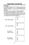
- Page 30: Fonctions d’utilisation Le ventilateur peut fonctionner en basse ou haute vitesse. Appuyez sur le bouton pour sélectionner une option de ventilateur. La sélection sera verrouillée après 8 secondes. Les options « Auto » activent le ventilateur seulement dans le cycle de refroidissement ou de chauffage. Les options de fonctionnement en continu (On) activent le ventilateur en permanence y compris en mode « OFF ». Ces options peuvent être désactivées dans le mode de configuration du thermostat.
- Page 31: Essai du thermostat Problème Solution Assurez-vous que la tension est de 24 VAC; l’appareil ne fonctionnera pas sans cette tension. Le système de ventilation ne se met pas en marche correctement. Aucun bouton du thermostat ne fonctionne. Le thermostat s’allume et s’éteint trop fréquemment. Ajustez l’écart de température. Le ventilateur ne s’arrête pas. La température de la pièce est erronée. Le compresseur ne fonctionne pas ou s’éteint immédiatement après une modification. Il y a une temporisation de trois minutes pour le compresseur lorsqu’il se met en marche et s’arrête. Pressez le bouton Reset une fois pour réinitialiser le microprocesseur du thermostat.
- Page 32: Garantie limitée du thermostat Une preuve de la date d’achat originale est nécessaire pour valider la garantie. GE Appliances remplacera un thermostat comportant un défaut de matériaux ou de fabrication pendant un an à compter de la date du premier achat. Pour le remplacement sous garantie, contactez votre distributeur. Ce que GE Appliances ne couvre pas inclut les frais de déplacement pour réparation vers votre emplacement et une installation mal effectuée. Vous êtes responsable d’effectuer correctement les raccords électriques de votre produit. Les dommages causés par des modifications au produit ou par son usage déraisonnable ne sont pas couverts. Cette garantie limitée est consentie à son premier acheteur et à tout propriétaire subséquent pour les produits achetés pour utilisation aux États-Unis et au Canada. En Alaska, la garantie limitée exclut les frais d’expédition ou les appels de service vers votre site. Cette garantie limitée vous donne des droits légaux spécifiques, et vous pouvez également avoir d’autres droits qui varient d’un état ou d’une province à l’autre. Garant : GE Appliances, Louisville, KY 40225

BACKER ELECTRIC BMST 7 Backermatic Safety Thermostat Instructions

DEVI 330 Electronic Thermostat Installation Guide

BEOK Color TFT-LCD Heating Thermostat User Manual

Honeywell RTH8500 Wifi Thermostat User Manual

EPH CONTROLS CDTP2 Hardwired Room Thermostat Instruction Manual

velleman VM148 Programmable Thermostat Instruction Manual

EUROLAMP HY08BW Digital Heating Smart Thermostat User Manual

GENERAL LIFE HT25S RF Wireless Room Thermostat User Manual

qunda QD-HVAC15 WIFI Touch-Screen Programmable Thermostat Instruction Manual

PRAXISDIENST DZ 003 Dry Block Thermostat User Manual