
Home > ENGO CONTROLS > ENGO CONTROLS E10-MBUSW, E10-MBUSB Wi-Fi MODBUS Thermostat User Guide
ENGO CONTROLS E10-MBUSW, E10-MBUSB Wi-Fi MODBUS Thermostat User Guide

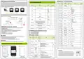


General information about MODBUS RTU
HOLDING registers – for reading and writing
RS-485 communication settings
The MODBUS RTU structure uses a master-slave system to exchange messages. It allows a maximum of 247
slaves to be connected, but only one master. The master controls the operation of the network and only it sends
the request. The slaves do not undertake the transmission themselves. Each communication starts with the
master making a request to the Slave, which responds to the master with what has been asked of it. The master
(computer) communicates with the slaves thermostats in two-wire RS-485 mode. This uses data lines A+ and
B- for data exchange, which MUST be one twisted pair
Adress
Access
Description
Value range
Means
Default
Parameter
Adress
Description
Value
1-247
Default value
R/W
Engo MODBUS
0
0x0000
1-247
ID
1
1
(#04)
- online ID number
R/W
0=OFF
1=ON
master
SLAVE 1
SLAVE 2
SLAVE X
MODBUS Slave device address (ID).
1
257 0x0101
258 0x0102
Power on/off
0,1
(#06)
0=Manual mode
1=Program mode
2=Holiday mode
3=Frost mode
1 = 4800
2 = 9600
3 = 19200
4 = 38400
R/W
Operation mode
0,1,2,3
0
Baud
Baud
2
(
#06)
R/W
0=Unlocked
1=Locked
262 0x0106
263 0x0107
264 0x0108
Child lock
0,1
0
60
0
(#06)
Data
Parity
StopBit
Data bites
8 bits
8
0
1
No more than two cables can be connected to each terminal, ensuring that a‘Daisy Chain’(in series) or‘straight
line’ (direct) configuration is used. Star or network (open) connection is not recommended as reflections
within the cable can cause data corruption.
R/W
Backlight brightness
Ambient Backlight Level
0-100
0-10
N-> Brightness=N%
N-> Bridgness=N%
(#06)
0 = lack
1 = even
2 = odd
Parity bit
- sets data parity for error detection
Daisy Chain (serial connection)
R/W
(#06)
1 = 1 stop bit
2 = 2 stop bit
0 = TPI UFH,
Stop bits
1 = TPI RAD,
R/W
265 0x0109
Control type
0-10
2 = TPI ELE,
0
Star connection
Net connection
(#06)
The minimum time from when a slave receives
a request until it returns a response. This makes
it possible to send data to free masters without
overloading the recipient.
3 = Histeresis 0.2 (+/-1C)....
... 10 = Histeresis 4.0 (+/-2C)
Response delay
0-255 ms.
0
R/W
268 0x010C
269 0x010D
270 0x010E
273 0x0111
274 0x0112
275 0x0113
279 0x0117
280 0x0118
285 0x011D
287 0x011F
288 0x0120
Clock minutes
Clock hours
0-59
0-23
1~7
Minutes
Hours
0
0
(#06)
The maximum time to wait to receive a response
from the slave device.
Response timeout
Interframe spacing
0,1-25,5 seconds
3,5-25 signs
10
R/W
(#06)
MODBUS RTU network operation - Slave mode
R/W
Clock Week Day
(1=Monday)
At least 3.5 characters (28 bits) of silence
between frames.
The Engo MODBUS controller has the following characteristics when operating as a slave device
in a MODBUS RTU network:
- Network connection via RS485 serial interface.
- Address, communication speed and byte format defined by hardware configuration.
- Allows access to all tags and data used in the controller ladder program.
- 8-bit slave address
Week day
3
3.5
(#06)
R/W
Setpoint temp in
program mode
50-450 N-> temp=N/10 °C
50-450 N-> temp=N/10 °C
210
210
50
350
50
0
(#06)
E10 MODBUS supports the following function codes:
#03 - reading n registers (Holding Registers)
#04 - reading n registers (Input Registers)
#06 - write 1 register (Holding Register)
R/W
Setpoint temp in
manual mode
- 32-bit data size (1 address = 32-bit data return)
- each MODBUS data register has a size of 2 bytes.
(#06)
R/W
Frost protection
setpoint
50
N->temp=N/10 °C
INPUT registers - read only
(#06)
ATTENTION:
R/W
Before the controller is connected to the RS-485 network, it must first be properly configured. The
controller’s communication parameters can be set in two ways:
- through configuration from the ENGO Smart application
Max setpoint temp
Min setpoint temp
Offset temperature
Relay type
50-450 N-> temp=N/10 °C
50-450 N-> temp=N/10 °C
-3.5...3.5°C in steps of 0,5C
Value
(#06)
Adress
Access
Description
Means
Default
range
R/W
- or by connecting it to a MASTER computer (e.g. via a USB/RS-485 converter)
(#06)
R
Firmware
Version
0x0001-
0x9999
ATTENTION:
Connecting unconfigured controllers to the RS-485 network results in their incorrect operation.
R/W
1
2
3
0x0001
0x1110=1.1.10 (BCD code)
(
#03)
(#06)
R/W
0 = NO
0,1
0b00000000=Idle, switch OFF
0b10000001=Heating
0
RS-485 communication settings of the controller in the app
(#06)
1 = NC
R
0x0002
0x0003
Working state
0b10000010=Heating & Frost protection
0b10001000=Cooling
0xff
(
#03)
R/W
0 = Heating
0,1
To access Modbus settings in the controller, follow these steps:
Heating/Cooling Selection
0
(#06)
1 = Cooling
0b00001000=Idle, sensor error
1
3
2
Value of the
Integrated
temperature
sensor, °C
R
50 - 450 N-> temp=N/10 °C
(
#03)
Factory reset
0 - No alarm
To RESET Thermostat to factory settings, hold down the
&
R
Fault
12 0x000C
13 0x000D
0,1,2 1 - No connection to the cloud
2 - No connection to Wi-Fi network
0
0
buttons until the FA message appears. Then release the keys.
Thermostat will restart, restore default factory settings and displays
the home screen. The device will be also removed from app. Factory
reset can be done within 5 minutes after power supply connection. If
thermostat is connected longer - factory reset cannot be performed.
(
#03)
information
0 - No alarm
Alert message
- problems with
the internal
1 - Temperature measured below 5C (LO)
R
0,1,2,3,4 2 - Temperature measured above 45C (HI)
3 - Short circuit in the internal temperature sensor circuit
4 - break in the internal temperature sensor circuit
8 sec.
8 sec.
(
#03)
In the application select:
„Modbus”.
Confirm with„Next”.
In Modbus settings
you can edit the parameters.
temperature sensor

| General | Details |
|---|---|
| Name | ENGO CONTROLS E10-MBUSW, E10-MBUSB Wi-Fi MODBUS Thermostat User Guide |
| Make | ENGO CONTROLS |
| Language | English |
| Filetype | PDF (Download) |
| File size | 0.26 MB |
 (1 votes, average: 5.00 out of 5)
 Loading...

ENGO Controls EONE230W Internet Controlled Thermostat User Guide

ENGO CONTROLS EFAN-230W Fan Coil Thermostat User Guide

ENGO CONTROLS FAN-24W 24V Fan Coil Thermostat User Guide

ENGO CONTROLS EASY230W Non-Programmable Wired Thermostat User Guide

ENGO CONTROLS EONE230 Internet Controlled Thermostat User Guide

ENGO CONTROLS EONEBATW, EONEBATB Internet Controlled Thermostat User Manual

ENGO Controls E901WIFI Internet Wireless Thermostat User Guide

ENGO CONTROLS EONE-BATW, EONE-BATB Internet Controlled Thermostat User Guide

ENGO CONTROLS EFAN-24W Fan Coil Thermostat User Guide

ENGO CONTROLS EFAN-230W WIFI 230V Fan Coil Thermostat User Guide


Roth SL Car Air Conditioner Thermostat Instructions

GREYSTONE TLDCB24J01 Flexible Copper Duct Average Low Limit Thermostat Instruction Manual

EMERSON 1F75H-21NP Non Programmable Heat Pump Thermostat Instruction Manual

Danfoss RAV Ally Radiator Thermostat User Guide
ENGO CONTROLS EONE-BATW, EONE-BATB Internet Controlled Thermostat User Guide

Fantini Cosmi C820RQ LED Thermostat User Manual

HIVE 852031 Mini Wireless Heating Smart Thermostat Instructions

Honeywell T841A,B Easy-To-SeeTM Heat Pump Thermostat Instruction Manual

Danfoss 015G3090 React Radiator Thermostat Installation Guide

beok TDR89 Wi-Fi Thermostat User Guide