EMERSON 1F75H-21NP Non Programmable Heat Pump Thermostat Instruction Manual

2 1 0 2
e m e r s o n .
3 . 7 - 7 8 4 2 0 A 0 P R 1 T N O
3 - 3 / 4 ” H x 6 ” W x 1 . . - . 1 . . / . 8 . . ” . . D . . . . . . . . . . . . . . . . .
o + 6 5 ° C ( ) - 2 ° F 9 ° t 1 5 0 ° F t - o 2 0 + . . . . . . . . . . R . . a . . n . . g . . e .
% n 9 0 o n - c o n d e n s i n g m a x i m . . u . . m . . . . . . . . . . . . . . . . . . . . . . . . . . . O . . p e r a t i n g
T h e r m o s t a
e T m p e r a t u r S e h i p p i n g
o 3 7 ° C )
o + 4 1 ° C )
o + 9 9 ° 3 F 2 ( ° 0 F t
o + 1 0 5 3 ° 2 F ° F ( 0 t ° t
. . e . . . . . . . . . . . e . . R . . t . a . u a n . . r . g .
e m y p T e r D i s p l a
. . . . . . . . . . . . . . . . . . . . . . . . . . . . . . O . . . p . e r a t i n g
. . . . . . . . . . . . . . . . . . . . . . . A . . u . . x . . i . l . i a . . r . . y . . H . e a t
. . . . . . . . C . . o . . o . . l . ) . . . . . . . . . . . . . H . . e . . a t P u m p (
. . . . 1 . . . . 7 . . ° . F . . . . . . . . . . . . . . . . . . . H . . e . a t P u m p ( H
0 . 7 5 ° F 5 . ° 0 1 F . 9 ° F
9 . ° 0 F
1 . 7 ° F
1 . 2 ° F
1 . 2 ° F
0 . 9 ° F
F a s t
S l o w
M e d
3 7 ° t o C ) 7 ° F ( 9 9 ° t o 4 5 °
° F 6 / H r ) :
R a t e d D i ff e
. . . . . . . . . . . . . . . . . . . . . . . . S . . e . . t . . p . . o . . i n . . t . . . R .
. . . . . . . . . . . . . . . . . . . . . e . . T r . m . . . i . n . . a . . l . L . . o . . a . .
. . . . . . . . . . . . . . . . - . H . . . a . r . . d . I . w n . . p i . r . u . e . t . . . . .
. . . . . . . o . . . w . . e . . r . . . . . . . . B . . a . . t . t . . e . . r . y . . P . . .
E l e c t r i c a l R
A m 2 a . 5 x i m u m a l l t e r m A i p n e 1 a r . l 5 s t e c r o m m i n b a i n l , e d
C l a s s I I , C , A N V E C 3 0 t o 2 0
H z 6 / 0 5 0
H z 5 0 / 6 0 C l a s s I I , C , A N V E C 3 0 t o 2 0
T I O N S
S P E C
.
o n d i s p o s i n g o f p r o d u c t s c o n t a i n i n g m e r c u r y
f o r i n f o r m a t - i o r e n c y c l e . o r g . t h e r m w o w s w t a t e f R e r t o
m e r c u r y m u s t n o t b e d i s c a r d e d i n h o u s e h o l d t r a s h .
. M e r c u r y a n d p r o d u c t t s h c a o t n c t o a n i n t a i n i n g s m e r c u r y
, t h v i s e p r r o d u . H c t o m w a e y m r e e p r l c a u c r e y a p r o d u c t
T h i s p r T o d I C u E c : t d o e s n o t M c o E n R t a C i U n R Y N O
8
H o m e o w n e
r o T u b l e s h o o t
6 - 7
5
O v e r v i e w T h e r m o s t a t
t h e T h U e r s m i n o g s t a t
I n s t a l l e r M e
H e a t
A u x / E m S t 1 e a r g g e e n c y
5
S y s t
2 / 1
, H e a t P u m p C o m p r S e t s a s g o e r S i n g l
3 - 4
2
H e a t / C o o l
S t a g e s
M a x i m u m
W i r i n g
A p p l i c a t i o n s T h e r m o s t a t
2 - 4
T h e r m o s t a
I N D E
” H 4 x 1 / 2 ” W 6 3 / 4
F 6 1 - 2 6 6 3 - U p P l C a o t e v e r
,
W a l l
c e s A s c o r y : O p t i o n a l
g a e 7 S e e p
e p l
d a e S m i m
a m m o g i P n r r g
C o m m o n
T h e r m P o u s m t a p t H e a t
O p e r a t i n g I n s t r u I c n t s i t o a n l l s
o w e r e d o B r H a t a t r e d r w y P i r e d w i t h
)
( N o n - P r o g r a 1 m F m 7

| General | Details |
|---|---|
| Name | EMERSON 1F75H-21NP Non Programmable Heat Pump Thermostat Instruction Manual |
| Make | Emerson |
| Language | English |
| Filetype | PDF (Download) |
| File size | 0.69 MB |


EMERSON ST75W Sensi Touch Wi-Fi Smart Thermostat Installation Guide

EMERSON Thermostat Common Wire Kit SA11 Instruction Manual

EMERSON 1F75H-21PR Programmable Heat Pump Thermostat Instruction Manual

EMERSON 1F75C-11PR Programmable Thermostat Installation Guide

EMERSON 1D56-310 White-Rodgers Low Voltage Horizontal Mounting Thermostat Instruction Manual

EMERSON Programmable Touchscreen Thermostat Setup in E2 and Site Supervisor User Guide

EMERSON 1F76U-22WFB Series Sensi Lite Smart Thermostat Installation Guide

EMERSON 1F87U-42WF Sensi Smart Thermostat User Guide

EMERSON 1F83C-11NP Single Stage Thermostat Owner’s Manual

EMERSON 1F75P-21PR Display Thermostat Instruction Manual

EMERSON 1F75H-21NP Non Programmable Heat Pump Thermostat Instruction Manual Overview
Summary of Contents
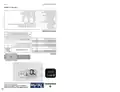
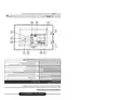
- Page 1: - The thermostat is designed for heat pump systems. - It operates within a temperature range of 6.5 °C to 37 °C. - The maximum non-condensing operating temperature is 150 °F. - The document includes information on electrical specifications. - Proper disposal of products containing mercury is emphasized. - The thermostat supports air source or geothermal systems. - It outlines maximum wiring applications for heat and cool stages. - The document provides troubleshooting guidance for homeowners. - Installation instructions for the thermostat are included. - The thermostat is compatible with various auxiliary heating sources.
- Page 2: Do not install until installation is complete. Do not use damaged equipment. Disconnect electrical power to the system. All wiring will not affect thermostat operation. Heat mode is for auxiliary only. Common wire is necessary for operation. Wiring tables show specific system instructions. Higher voltage causes shock or fire hazards. Do not show damage or property damage. Thermostat menu is found in the manual.
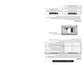
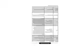
- Page 3: - Minimum set point for cool mode is 66 to 45. - Maximum set point for heat mode is 65 to 47. - Maximum heat limit is 60. - Compressor lock protects the compressor from short cycling. - Auxiliary heat will turn on based on specific conditions. - Fast medium mode will activate cooling at 35. - Fast medium mode will activate auxiliary heat at 30. - Hold menu settings to access default settings. - This will isolate both terminals to prevent unintended operation. - Ensure proper wiring connections to avoid issues.
- Page 4: The cooling system has a delay before the compressor starts. The thermostat will stop to adjust the temperature. The blower should be below the timing temperature. The auxiliary heating system should adjust to the room temperature. The heating system should stop to adjust the temperature. The heat pump should adjust to the room temperature. The blower should stop to operate properly. The backlight always remains on. Adjust the displayed temperature to Celsius or Fahrenheit. Default settings description is provided.
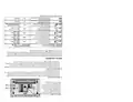
- Page 5: Before leaving, ensure the device is not left in an occupied state for an extended period. The display may indicate new parameters set for the device. The thermostat set point will be reached when the temperature is adjusted. Battery status indicators are crucial for monitoring device performance. The auxiliary mode will operate in heat mode when necessary. The system will indicate when it is running in cool mode. The thermostat protects the equipment from overheating. Ensure the device is properly set before use. Check the display for any alerts or status updates. Follow the instructions for optimal performance and safety.
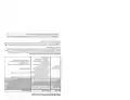
- Page 6: - The thermostat display can be adjusted. - Check each wire connection to verify the thermostat. - If the condition persists, contact a service professional. - Replacement service for the thermostat may be required. - Engage safety interlock or door switch. - Ensure door panel is in proper position. - No heat system may indicate a blown fuse or tripped circuit. - Corrective actions may be necessary for troubleshooting. - Possible symptoms include no cooling or heating. - Diagnostic procedures should be followed for system issues.
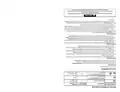
- Page 7: This product is designed to operate efficiently. The thermostat settings can be adjusted by the user. If the outdoor unit detects an issue, it will display an error. The thermostat may reset after two minutes. If the thermostat states No Heat, corrective action is required. The heating system may not be able to maintain the desired temperature. Digital thermostats provide precise control. The location of the thermostat affects its performance. The system cycles more frequently than older mechanical models. Corrective actions may be necessary for various symptoms.
- Page 8: Page 8

HIVE 852031 Mini Wireless Heating Smart Thermostat Instructions

tuya Mi-750 WiFi Smart Thermostat Instruction Manual

GENERAL LIFE Senna 270S RF Wireless Room Thermostat User Manual
EMERSON ST75W Sensi Touch Wi-Fi Smart Thermostat Installation Guide

EPH CONTROLS RFRB RF Room Cylinder Thermostat Instruction Manual

SALUS Thermostat and Smart Plug Installation Guide

Honeywell PRO 4110D Programmable Thermostat Installation Guide

GENERAL FH101S Underfloor Heating Thermostat User Manual

SECURE ThermoPlus AS2 Programmable Room Thermostat Instruction Manual

SALUS RT310RF Digital Wireless Central Heating Room Thermostat User Manual