Get the free PDF manual for the Doit 474053 Low Voltage Thermostat Installation Guide and access setup steps, usage instructions, and troubleshooting tips. 👉 View online or download now to keep your thermostat running smoothly!
Doit 474053 Low Voltage Thermostat Installation Guide Overview
Summary of Contents
Page 1: Installation and operation guide for model no. 474053 low voltage thermostat. The system can be set to off, auto, heat, or cool. Operator is advised to save the booklet for future use.
Page 2: About your new thermostat You have selected the 474053 low voltage heating/cooling thermostat. The sensitive spiral bimetal temperature sensor is combined with an adjustable heating anticipator and a fixed cooling anticipator to provide maximum comfort. Your new thermostat is easy to install and operate. You only need one regular screwdriver and a level — all other hardware is included. Please read this manual thoroughly before installing or operating your thermostat.
Page 3: In this guide, precautions are outlined on page 4. Specifications can be found on page 6. Instructions for installing your thermostat start on page 7, including checking the thermostat location, routing wires to the location, and wiring and attaching the thermostat. Operating your thermostat is discussed on page 22. Maintenance information is provided on page 24, covering adjusting the heat anticipator and calibrating the thermostat. It is advised to save this booklet for future use.
Page 4: Precautions If in doubt whether your wiring is millivolt, line, or low voltage, have the wiring inspected by a qualified heating and air contractor, electrician, or someone familiar with basic electricity and wiring. Do not exceed the specification ratings. All wiring must conform to local and national electrical codes and ordinances. This control is a precision instrument and should be handled carefully. Rough handling or distorting components could cause the control to malfunction.
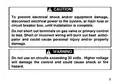
Page 5: Caution: To prevent electrical shock and/or equipment damage, disconnect electrical power to the system until installation is complete. Do not short out terminals on gas valve or primary control to test. Short or incorrect wiring will burn out heat anticipator and could cause personal injury and/or property damage. Warning: Do not use on circuits exceeding 30 volts. Higher voltage will damage the control and could cause shock or fire hazard.
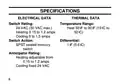
Page 6: Specifications Electrical data Thermal data Switch rating Temperature range Heat 50°F to 90°F (10°C to 32°C) 24 VAC (30 VAC max.) Heating 0.15 to 1.2 amps Cooling 0 to 1.5 amps Switch action Differential: 1°F (0.6°C)
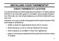
Page 7: Installing your thermostat You should install your thermostat about five feet (1.5 meters) above the floor in an area with good air circulation and average temperature. Normally, you can simply replace your old thermostat with your new one. You may consider changing the thermostat’s location if the thermostat is affected by drafts or dead air spots behind doors and in corners. Direct exposure to hot or cold air blowing from ducts can also affect the thermostat's performance. Direct exposure to sunlight or heat from appliances should be avoided. Pipes or chimneys located behind the wall where the thermostat is situated can impact its accuracy.
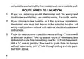
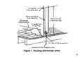
Page 8: Route wires to location. If you are replacing an old thermostat and the wiring and location are satisfactory, use existing wiring. If in doubt, rewire. If you choose a new location or if this is a new installation, thermostat wire must first be run to the selected location. All wiring must conform to local and national electrical codes and ordinances. Probe for obstructions in partition before drilling a 1/2” hole in wall at selected location. Take up quarter round (if necessary) and drill a small guide hole for sighting. From basement, drill a 3/4” hole in partition floor next to guide hole. In houses without basements, drill a 1/2” hole through ceiling and into partition from above.
Page 9: Through this hole, drop a light chain or 6” chain attached to a strong cord. Snag cord in basement with hooked wire. In houses without basements, drop cord through hole in ceiling and down partitioning; snag the cord at thermostat location. Attach thermostat wire to cord or chain and pull wire through hole in wall so that at least 6” of wire protrudes. To prevent electrical shock and/or equipment damage, disconnect electrical power to system, at main fuse or circuit breaker box, until installation is complete.
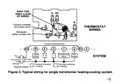
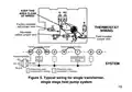
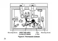
Page 10: The typical wiring diagrams show only the terminal identification and wiring hookup. Always refer to wiring instructions provided by equipment manufacturer for system hookup operation. All wiring must conform to national and local electrical codes and ordinances. Remove cover from thermostat by gripping the base in one hand. Use the other hand to pull gently at the top or bottom of the cover. Carefully remove the shipping protective packing from the switch. Pull wires through the opening in the thermostat base and connect wires beneath the terminal screws.
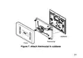
Page 11: Push excess wiring back into the wall and plug the hole with fire-resistant material to prevent drafts from affecting thermostat operation. Position the thermostat base over the hole in the wall and mark mounting hole locations. Drill mounting holes. Fasten the base loosely to the wall using mounting screws, level it, and tighten the screws to secure the base. If holes in the wall are too large, use plastic screw anchors. Snap the cover on the thermostat base and set the temperature lever to the desired setpoint. Turn on electrical power to the system.
Page 12: All wiring diagrams are for typical systems only. Always refer to equipment manufacturer’s instructions for system hookup operations. Do not allow wiring to pinch between the subbase and the wall. Be certain that the pivot post that protrudes from the rear of the thermostat does not rub the insulation of any wires. Tighten all screws securely - some serve as electrical connections. The subbase as shipped may not operate the fan correctly. If both the heating and cooling system must operate the fan relay, remove the moveable yellow jumper wire from the Y terminal and connect it to the A terminal. The fan should now cycle when the thermostat calls for either heat or cool.
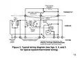
Page 13: Keep this area clear of wires. Factory-installed red jumper wire. Moveable yellow jumper wire. Heat relay. Compressor relay. Fan relay. Terminal energized in cooling. Terminal energized in heating. Typical wiring for single transformer heating/cooling system.
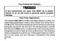
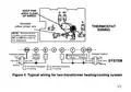
Page 14: Two-transformer systems Caution: If two transformers are used, they must be in phase. Failure to do so will result in personal and/or property damage. Heat pump applications: This subbase will not provide multi-stage heating or cooling. For single stage applications, install a short jumper wire across terminals W and Y. If the old thermostat has a terminal that is continuously energized, disconnect the wire from the old thermostat’s terminal and connect it either to the B terminal or to the O terminal. If the system heats on a call for cool or vice versa, this wire has been connected to the wrong terminal.
Page 15: Keep this area clear of wires. Remove factory-installed jumper between RC and RH terminals for this application. Typical wiring for two-transformer heating/cooling system. Hot 120 VAC. Neutral 120 VAC. 24 VAC. Heat relay. Compressor fan relay. Terminal energized in cooling. Terminal energized in heating.
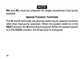
Page 16: RH and RC must be jumpered for single transformer heat pump systems. The B and O terminals can provide switching for special functions other than heat pump operation. When the system switch is in the HEAT position, the B terminal is energized. When the system switch is in the COOL position, the O terminal is energized.
Page 17: Keep this area clear of wires. Factory-installed red jumper wire. Moveable yellow jumper wire. Field-installed jumper wire. Factory-installed jumper. Field-installed jumper. Reversing valve energized in cooling. Reversing valve energized in heating. Typical wiring for single transformer, single stage heat pump system.
Page 18: Keep this area clear of wires. Mounting screw. Thermostat subbase.
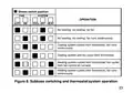
Page 20: Operating your thermostat is straightforward. The heating and cooling system and fan operation are controlled by various switch positions. Use the system switch to select heating, cooling, or to turn the system off. The fan switch controls fan operation. In the AUTO position, the fan cycles with the heating or cooling system. The fan will not run if the system switch is OFF and the fan switch is in AUTO. In the ON position, the fan runs continuously, regardless of the system switch position.
Page 21: Shows switch position for fan and system operation. Auto on, cool off, heat settings are available. No heating, cooling, or fan operation is indicated. Fan runs continuously with no heating or cooling. Cooling system cycles from thermostat while fan runs continuously. Cooling system and fan cycle from thermostat. Heating system cycles from thermostat with fan control on furnace. Heating system cycles from thermostat while fan runs continuously. Figure 8 illustrates subbase switching and thermostat/system operation.
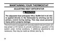
Page 22: Maintaining your thermostat involves adjusting the heat anticipator. The adjustable heat anticipator will burn out if 25 VAC is applied directly to the thermostat by shorting out the primary control during testing. This may cause personal injury and/or property damage. The thermostat is equipped with an adjustable heat anticipator and was preset at the factory to provide satisfactory operation of the system under normal conditions. If additional adjustments are necessary, they may be made as indicated.
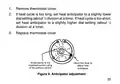
Page 23: Remove thermostat cover. If heat cycle is too long, set heat anticipator to a slightly lower dial setting. If heat cycle is too short, set heat anticipator to a slightly higher dial setting. Replace thermostat cover. Arrow points to the matched current rating of the primary control. Move this lever to adjust heat anticipator. Figure 9. Anticipator adjustment.
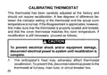
Page 24: Calibrating thermostat This thermostat has been carefully adjusted at the factory and should not require recalibration. A few degrees of difference between the indicator setting of the thermostat and the actual room temperature is normal. If the disagreement is appreciable, first make sure that the thermostat is properly located and leveled, and that the cover thermostat matches the room temperature. If recalibration is still necessary, proceed as follows. To prevent electrical shock and/or equipment damage, disconnect electrical power to the system until recalibration is complete. The anticipator’s heat may adversely affect thermostat recalibration. To prevent this, disconnect electrical power to the thermostat at the furnace, main fuse, or circuit breaker box.
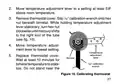
Page 25: Move the temperature adjustment lever to a setting at least 5°F above room temperature. Remove the thermostat cover. Slip the 7/32” calibration wrench onto the hex nut beneath the bimetal. While holding the temperature adjustment lever stationary, turn the hex nut clockwise until mercury shifts to the right end of the tube. Move the temperature adjustment lever to the lowest setting. Replace the thermostat cover. Wait at least 10 minutes for bimetal temperature to stabilize. Do not stand near the 7/32” calibration wrench. Figure 10 illustrates calibrating the thermostat.
Page 26: Move the temperature adjustment lever to match actual room temperature. Remove the thermostat cover. Slip calibration wrench onto hex nut. Hold the temperature adjustment lever stationary while turning the hex nut counter-clockwise. Turn until mercury just barely shifts to the left end of the tube. Replace the thermostat cover. Set the temperature adjustment lever to the desired setpoint. Turn on electrical power to the system and thermostat. Avoid breathing on the thermostat during calibration. Ensure body heat does not affect bimetal temperature.