
sinope TH1300ZB-C4 3600W Smart Floor Heating Thermostat Installation Guide
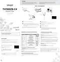


CONNECT YOUR THERMOSTAT TO A CONTROL4 HOME AUTOMATION SYSTEM
CONNECT AN EXPANSION UNIT (TR1310)
It is possible to connect up to 10 expansion units to the
same device. (EXP function)
2
1
TH1300ZB-C4
TR1310
TR1310
Initiate the connectivity
session of your Control4
controller by referring to
the device's user guide.
Connect your thermostat to the network
by pressing simultaneously on the
and
buttons.
On the thermostat display:
Flashes: Connecting
Remains lit: Connected
If the connectivity fails, the
symbol will
disappear from the display. Refer to our
Website to troubleshoot the unit.
To others
TR1310
CONNECT THE AUXILIARY OUTPUT
3
4
Second heating stage (15 sec / 15 min functions)
Connect all your thermostats
the same way, by going to the
next closest thermostat.
When all the thermostats are
connected, close the
connectivity session of your
Control4 controller.
3rd
1st
2nd
Controller
Transformer
24 VAC
Baseboard
Convector
DISCONNECT YOUR THERMOSTAT FROM A CONTROL4 HOME AUTOMATION SYSTEM
To disconnect your thermostat from the Control4 controller, press the
symbol will disappear from the display.
and
buttons simultaneously for 10 seconds. The
GROUND FAULT PROTECTION
TECHNICAL SPECIFICATIONS
The thermostat is equipped with a ground fault protection that can detect a
current leakage of 5 mA. When a current leakage is detected, the ground fault
protection is triggered and quickly interrupts the power supply to prevent any
serious injuries.
Operating voltage: 120/208/240 Vac, 50/60 Hz
Maximum load:
1800 W @ 120 V / 15 A
Transmitter Module IC : 22394-ZBM1501 / FCC ID:2AK2T-ZBM1501
This device complies with Industry Canada license exempt RSS standard(s). Operation is subject to
the following two conditions:
3120 W @ 208 V / 15 A
3600 W @ 240 V / 15 A
Resetting the ground fault protection
The RESET button warning light turns ON (red) when the ground fault protection is
triggered. If the RESET button warning light turns ON during normal operation of
the thermostat, simply press the RESET button to reset the ground fault protection.
The light will turn OFF. If, for any reason, this situation occurs again, cut the power
to the heating system from the main electrical panel and ask an electrician to
verify the installation.
(1) this device does not cause interference, and (2) this device must accept any interference,
including interference that may cause undesired operation of the device.
This equipment has been tested and found to comply with the limits for a Class B digital device,
pursuant to part 15 of the FCC Rules. These limits are designed to provide reasonable protection
against harmful interference in a residential installation. This equipment generates, uses and can
radiate radio frequency energy, and if not installed and used in accordance with the instructions,
may cause harmful interference to radio communications. However, there is no guarantee that
interference will not occur in a particular installation. If this equipment does cause harmful
interference to radio or television reception, which can be determined by turning the equipment
OFF and ON, the user is encouraged to try to correct the interference by one or more of the
following measures:
Setpoint range: 5 °C to 36 °C (41 °F to 97 °F)
Display range: 0 °C to 50 °C (32 °F to 99 °F)
Resolution: 0.5 °C ( 1 °F)
Storage: -20 °C to 50 °C (-4 °F to 122 °F)
Auxiliary output: 24 Vac / Vdc / 0.1 A
GFCI protection: Class A (5mA)
Zigbee profile 3.0
Testing the ground fault protection
This thermostat has an Auto Test which
periodically verifies the correct operation of
the protection circuit. You can also do this
manually:
Frequency: 2.4 GHz
Transmission power: +20 dBm
Receiver sensitivity: -108 dBm
Reorient or relocate the receiving antenna.
Increase the separation between the equipment and receiver.
Connect the equipment into an outlet on a circuit
different from that to which the receiver is connected.
Consult the dealer or an experienced radio/TV technician for help.
1) Press the TEST button. If the RESET button's
red warning light does not turn ON, the test
has failed. Cut the power to the heating
system from the main electrical panel and
ask an electrician to verify the installation.
3-year limited warranty
SINOPE TECHNOLOGIES INC. warrants the components of their products against
defects in material and workmanship for a 3-year period from the date of purchase,
under normal use and service, when proof of purchase of such is provided to the
manufacturer. This warranty does not cover any transportation costs that may be
incurred by the consumer. Nor does it cover a product that has been improperly
installed, misused or accidentally damaged.
2) Press the RESET button to restart the
thermostat's base.
The obligation of SINOPÉ TECHNOLOGIES INC., under the terms of this warranty, will
be to supply a new unit and this releases the manufacturer from paying the
installation costs or other secondary charges linked to replacing the unit or the
components.
TROUBLESHOOTING GUIDE
What should I do if the E1F code appears on my thermostat display?
The E1F code means that the thermostat is in “Floor” mode and there is no
connected sensor. If your thermostat is not intended to control an heated floor,
change the thermostat’s control mode for the “A mode”.
For more information, visit our Website:
660-0735-0014-B

| General | Details |
|---|---|
| Name | sinope TH1300ZB-C4 3600W Smart Floor Heating Thermostat Installation Guide |
| Make | sinope |
| Language | English |
| Filetype | PDF (Download) |
| File size | 1.01 MB |
 (1 votes, average: 5.00 out of 5)
 Loading...

sinope TH1134ZB-HC Smart Line Voltage Thermostat Owner’s Manual

sinope Smart Floor Heating Thermostat TH1310WF Installation Guide

sinope Smart Low Voltage Thermostat TH1400WF Installation Guide

sinope TH1124NP Non Programmable Thermostat for Electric Heating Owner’s Manual

sinope TH1400NP Non Programmable Low Voltage Thermostat Installation Guide

sinope TH1134ZB Smart Line Voltage Thermostat Installation Guide

sinope TH1500ZB Smart Double Pole Thermostat Installation Guide

sinope TH1500WF Smart Double Pole Thermostat Installation Guide


PECO T8168B-2 BACnet Proportional Thermostat Installation Guide

PowerOptimal Elon Smart Thermostat User Guide

KETOTEK KTF0155 Smart Thermostat User Manual

GENERAL LIFE 260S Digital Room Thermostat User Manual

GENERAL LIFE HT25 Smart Room Thermostat User Manual

BEOK TDS75WIFI Room Thermostat Instruction Manual

Wengart TP808-3 7 Day Programmable Thermostat User Manual

KINGHOME WK-010WC1 Smart Thermostat Owner’s Manual

ESi Controls ESRTERFW Wireless Digital Room Thermostat Installation Guide
MCOHome MH-5900 Z Wave Thermostat User Guide