PECO T8168 Performance Pro Thermostat Installation Guide


CONTROL
SYSTEMS
T8168B-2 BACnet® INSTALLATION GUIDE
THE PECO PERFORMANCE PRO™ T8168 THERMOSTAT
!
WARNING
▲
Thank you for choosing a PECO® Performance PRO™ T8168. The T8168 ther-
mostat is intended for commercial and residential enviroments. It supports both
programmable and non-programmable operation.
• READ THESE INSTRUCTIONS CAREFULLY BEFORE ATTEMPTING TO
INSTALL, OPERATE OR SERVICE THIS THERMOSTAT.
• Failure to observe safety information and comply with instructions could
result in PERSONAL INJURY, DEATH AND/OR PROPERTY DAMAGE.
• To avoid electrical shock or damage to equipment, disconnect power
before installing or servicing and use only wiring with insulation rated for full
thermostat operating voltage.
Key features include: auto-changeover; optional remote sensor; three levels of
keypad lockout with optional PIN access code; a heat/cool Demand Indicator;
up to four scheduled events per day, a 365-day calendar, 20 holidays, holiday
override and temporary override.
Applications
• Use care to avoid electrostatic discharge.
• To avoid potential fire and/or explosion do not use in potentially flammable
or explosive atmospheres.
The PECO® Performance PRO™ T8168 applications include fan coil, PTAC and
conventional system with a single, multi speed or 0-10 VDC Fan.
System Mode Selections: Off-Heat-Cool-Auto
ON-OFF Heat/Cool Outputs: Up to 2 Heat, 2 Cool
Proportional Heat/Cool Outputs: Three Wire Floating or 0-10 VDC Control
Fan Control: Cycling (Auto) or Continuous (On); Up to 3 Speeds or Staged
Permanent Memory: All device settings are stored in permanent memory.
Optional Connections: Remote Sensor, Pipe Sensor, Fault Detection and Setback
• Retain these instructions for future reference.
• This product, when installed, will be part of an engineered system whose
specifications and performance characteristics are not designed or
controlled by PECO® . Review applications and national and local codes to
assure that the installation will be functional and safe.
TECHNICAL SPECIFICATIONS
• WARNING: Disconnect power before beginning installation.
!
Temperature Control Range: 50° to 90° F (10° to 32° C)
Differential: 1° F (0.5°C)
▲
• CAUTION: Use copper wire only
Input Power: 24 VAC (20-30 VAC) 50/60 Hz (+/- 10%)
Terminal Connections: 14-24 AWG stranded or solid wire
Operating Temperature: 0° to 120°F (-18° to 49°C)
Shipping/Storage Temperature: -20° to 130°F (-29° to 54°C)
Operating Humidity: 5% to 95% RH, non-condensing
Physical Dimensions: 4.3” H x 5.7” W x 1.3”D
Proportional Output Band Width: 2°F (1°C)
RATINGS
Outputs: Y1, Y2, W1, W2, G, G1
24 VAC (20-30 VAC); 50/60 Hz
10 VA
Outputs: WD, GD, YD
Proportional Stroke Time Default: 2 Minutes (Configurable)
0-10 VDC: Loads must be 1.2K ohms minimum
4-20 mA: Loads must be 600 ohms maximum
This thermostat uses triacs switching for accuracy and quiet operation.
!
CAUTION!
▲
• 24 VAC low-voltage thermostat.
• Do not install on voltages higher than 30 VAC.
• Use copper wire only
• Use care to avoid electrostatic discharge to the thermostat.
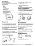
System Operation
SM 110
Service
Menu
1
2
3
4
5
6
7
8
9
10
11
12
13
1
4
15
16
Heat
TWF
1 Cool
2 Fan
TWF
Heat
1 Cool
3 Fan
TWF
Cool
1 Heat
2 Fan
1 Heat
1 Cool
1 Fan
2 Heat
1 Cool
1 Fan
1 Heat
1 Cool
3 Fan
2 Heat
1 Cool
3 Fan
2 Heat
2 Cool
2 Fan
Heat
Only
1 Fan
Cool
Only
1 Fan
Heat
Only
2 Fan
Cool
Only
2 Fan
Heat
Only
3 Fan
Cool
Only
3 Fan
TWF Heat
TWF Cool
2 Fan
0-10
VDC
Only
SYSTEM
TYPE
Cool
Open
Cool
Open
Y1
W1
Y2
Cool 1
Cool 1
Heat 1
-
Cool 1
Heat 1
Cool 1
Heat 1
Cool 1
Heat 1
COOL 2
Heat 2
-
Cool 1
-
Cool 1
-
Cool 1
-
Cool 1
Cool 1
-
-
Heat
Open
Heat
Open
Heat
Open
Heat 1
Heat 1
-
-
Cool 2
-
Heat 1
-
-
Cool 2
-
Heat 1
Heat 1
FAN
MED
FAN
MED
FAN
MED
FAN
MED
FAN
MED
Cool
Close
Cool
Close
-
-
Cool2
-
Heat
Close
Heat
Close
Heat
Close
W2
Heat 2
-
Heat 2
Heat 2
Heat 2
Heat 2
-
Heat 2
-
G
FAN
FAN
FAN HI
FAN HI
FAN HI
FAN
FAN
FAN HI
FAN HI
FAN HI
FAN HI
FAN HI
FAN HI
FAN HI
FAN HI
-
G1
Damper
Damper
FAN LO
FAN LO
FAN LO
Damper
Damper
FAN LO
FAN LO
FAN LO
FAN LO
FAN LO
FAN LO
FAN LO
FAN LO
Damper
YD
Cool 1
Heat 1
Cool 1
Heat 1
Cool 1
Heat 1
Cool 1
Heat 1
Cool 1
Heat 1
-
Cool 1
-
-
Cool 1
-
-
Cool 1
-
Cool 1
Heat 1
Cool 1
Heat 1
Cool 1
Heat 1
Cool 1
Heat 1
Cool 1
Heat 1
WD
Heat 1
Heat 1
Heat 1
• When System Fan Type (SM112) is set to 1 or 2 (0-10 VDC operation), the GD output is the only fan oputput and G1 provides Damper operation.
• When Fan Coil 2-Pipe operation is selected the W1 and WD outputs will be disabled. See SM 171.
© COPYRIGHT 2025 PECO, INC. ALL RIGHTS RESERVED.
P/N 74599 3220-2406 REV 02
1

| General | Details |
|---|---|
| Name | PECO T8168 Performance Pro Thermostat Installation Guide |
| Make | PECO |
| Language | English |
| Filetype | PDF (Download) |
| File size | 0.47 MB |


PECO T372P Thermostat Instruction Manual

PECO T8168B-2 BACnet Proportional Thermostat Installation Guide

PECO TW180 Thermostat Instruction Manual

PECO T8168 Performance Pro Thermostat Installation Guide Overview
Summary of Contents
- Page 1: Thank you for choosing a PECO Performance PRO™ T8168. The T8168 thermostat is intended for commercial and residential environments. It supports both programmable and non-programmable operation. Read these instructions carefully before attempting to install, operate or service this thermostat. Failure to observe safety information and comply with instructions could result in personal injury, death and/or property damage. Key features include: auto-changeover; optional remote sensor; three levels of keypad lockout with optional PIN access code; a heat/cool demand indicator; up to four scheduled events per day, a 365-day calendar, 20 holidays, holiday override and temporary override. The PECO Performance PRO™ T8168 applications include fan coil, PTAC and conventional system with a single, multi-speed or 0-10 VDC fan. Temperature control range: 50° to 90° F (10° to 32° C). Input power: 24 VAC (20-30 VAC) 50/60 Hz (+/- 10%). Operating temperature: 0° to 120°F (-18° to 49°C). This thermostat uses triacs switching for accuracy and quiet operation. Caution: Use copper wire only.
- Page 2: Installation instructions provide guidance on selecting a thermostat location and connecting power to the thermostat wall plate. The thermostat should be located about four feet above the floor on a wall with good ventilation and response to temperature changes. It operates on 24VAC power, and power must be turned off before making connections. The thermostat can be mounted on various types of device boxes or flat surfaces. Avoid placing the thermostat in areas affected by direct sunlight, drafts, or radiating heat. Mounting the wall plate involves positioning it correctly, drilling holes, and securing it with screws. Setting the clock, month, and day is recommended before advanced configuration. System test verification is important to ensure thermostat operation. Unused wires should be capped off and terminated according to local building codes. Configuration of the T8168 is done through service menus, which may have limited access based on other settings.
- Page 3: Programmable or non-programmable This thermostat is easily changed from non-programmable to programmable operation in Service Menu 100. Fan coil 2-pipe/4-pipe operation Service Menu 171 sets 2-pipe or 4-pipe fan coil operation. Output operation The T8168 uses System Types for control of 24 VAC ON-OFF fans and relays; three wire floating and proportional 0-10 VDC fans, valves and dampers. Pipe sensor: seasonal change over This feature is enabled when 2-pipe or 4-pipe operation is selected in Service Menu 171. 0-10 VDC fan hi-med-low operation User selection of 0-10 VDC (or 4-20mA) fan speed is as follows: HI, MED, LO. Damper operation A damper output is available when terminal G1 is not being used as a fan speed. System flush for fan coil valves Enable a periodic opening of valve(s) to flush valves and reduce sediment buildup. Accessory sensor connections Connect optional remote sensing, occupancy detection, door open or fault notification. Keypad lock out The keypad lockout function blocks access to features by hiding them from the user’s view/selectability. Setback An occupancy sensor can be used between S1 & SC terminals to change the thermostat control points to Setback Low and Setback High.
- Page 4: Terminal block designations Warning: Disconnect power before beginning installation Caution: Use copper wire only Connect the first 24 VAC signal to 24VAC1. Connect the second 24 VAC signal to 24 VAC2. Neither 24 VAC signal should be connected to ground. Confirm system type selection in Service Menu 110. Confirm fan operation in Service Menu 112. This thermostat will broadcast a Wi-Fi network on power up. Select the network and enter Password: 12345678, then press connect. Recommended wiring specification: 22 -24 AWG shielded twisted pair, low capacitance.
- Page 5: T8168 configuration service menus Service menu access The following service menus commonly require configuration. Please verify that these are set for your specific application. Hold lower right and lower left keys for five seconds. Press Next or Go Back button to select a service menu. Press ▲/ ▼ to select option. Press Done when complete. SM 100 = Programmable or Nonprogrammable SM 110 = System Type SM 112 = Fan Type SM 135 = W1 Heat Output NO or NC SM 170 = Remote Sensors SM 240 = Number of Programmable Events per Day SM 395 = Override Duration for Programmable Operation SM 340 = Keypad Lock Out When enabled, daylight savings time follows the US 2007 format. System types may disable some service menu availability. Error detection/notification can be set in Service Menu 175.
- Page 6: Fan Control (Heating) The thermostat will not activate the fan with a heating demand. The thermostat will activate the fan with heat demand. Configures digital cooling output for 0-10VDC or 4-20mA DC. Configures digital heating output for 0-10VDC or 4-20mA DC. Depending on SM 124 setting, sets Fan HI speed voltage or current (mA) at terminal GD with demand for Heat. Depending on SM 124 setting, sets Fan HI speed voltage or current (mA) at terminal GD with demand for Cool. When using a remote sensor an open or short will turn off outputs and display either 2Ero(open) or 2Erc (closed). Enables fan coil pipe sensor operation. Changes to Cool when pipe temp is below threshold. Changes to Heat when pipe temp is above threshold.
- Page 7: Keypad Lockout This function blocks access to certain features of the device. The Service Menu is still available if the keypad lockout is enabled. If PIN is entered, keypad lockout is overridden for 5 minutes. Enable Pin Access Applies a 3-digit access code to enter service menu. Fan Mode Fan is always on, regardless of demand. Fan is only on with heating or cooling demand. User can choose either selection for fan operation. System Mode Sets the system modes the occupant is able to select. Hotel operation - For ease of use change available system modes to ON-AUTO. System Flush Enable Enables the flush function for fan coil systems. Failure to follow this instruction can result in damage to equipment and/or property. Flush Duration Defines how long to open the valve to perform the flush function. Minimum Dead band Adjustment A changeover dead band value prevents short cycling between heating and cooling modes. Pre-Occupancy Purge Energizes the lowest fan available for selected number of hours prior to events. Temporary Occupied Duration Limit Sets the duration of a user override for programmable operation. Minimum Off Time Sets the minimum off time for both the heat and cool output.
- Page 8: Factory default reset allows the device to return to factory settings. Cooling system output can be enabled for testing, activating the output for 10 minutes. Heating system output can also be enabled for testing, activating the output for 10 minutes. Fan system output test can activate based on service menu settings for 10 minutes. The IP address requires thermostat configuration and displays in four segments. The MSTP address also requires thermostat configuration and displays when entered. Device ID is displayed and set to 1, using UP and DN arrows. Troubleshooting section addresses common symptoms and potential causes. If the display screen is blank, check power wiring and settings. If heating or cooling systems do not respond, verify system type selection and wiring connections.

SUNSKY BHT-006 Series Thermostat Instruction Manual

EPH CONTROLS eTRV-HW Smart Cylinder Thermostat User Guide

Fantini Cosmi CH141E Battery Operated Weekly Programming Thermostat Owner’s Manual
Honeywell Home RTH Series T5 Smart Thermostat Installation Guide

Honeywell PCR-100 Electronic thermostat Instruction Manual

STIEBEL ELTRON FEB 2.1 Programming Thermostat Installation Guide

EPH CONTROLS CP4 Programmable RF Thermostat User Manual

BEOK TGW60 Glass Screen Thermostat Instruction Manual

tekmar IOM-T-560 Programmable Thermostat Instruction Manual

EMOS P5611OT Wireless Thermostat Instruction Manual