Home > Owon Technology > Owon Technology PCT 523-W-TY Tuya WiFi 24VAC Thermostat User Guide
Owon Technology PCT 523-W-TY Tuya WiFi 24VAC Thermostat User Guide


Wi-Fi Smaꢀ Thermostat
Quick Staꢀ Guide
| General | Details |
|---|---|
| Name | Owon Technology PCT 523-W-TY Tuya WiFi 24VAC Thermostat User Guide |
| Make | Owon Technology |
| Language | English |
| Filetype | PDF (Download) |
| File size | 1.75 MB |


Owon Technology PCT 523-W-TY Tuya WiFi 24VAC Thermostat User Guide Overview
Summary of Contents
- Page 1: Wi-Fi Smart Thermostat Quick Start Guide
- Page 2: Important information regarding safety instructions is highlighted. Failure to follow these safety instructions could result in fire, electric shock, or other injury or damage. In some regions, a professional installation may be necessary. Check local regulations and building codes before undertaking any electrical work. Permits and/or professional installation might be legally required. Before starting installation, turn off the power to the installation area at your circuit breaker or fuse box. Always handle electrical wiring with care to avoid the risk of electrical shock or equipment damage. Install your device away from heat sources and direct sunlight to prevent temperature fluctuations. Avoid placing your device near water or in areas with high humidity.
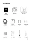
- Page 3: In the box Wi-Fi Backplate Trim plate Thermostat C-wire adapter (optional) Remote screws (x2) Dowel plugs Zone sensor (optional) Wire labels
- Page 4: These tools will help with installation. A drill with a 3/16-inch drill bit. A pencil. Pliers and wire strippers.
- Page 5: Turn off the power. Locate the power switch for the HVAC system and turn it off. This step is important for your safety and the safety of your home. Once the power is off, adjust your old thermostat to double check that the system is off. Remove your old thermostat faceplate. Some faceplates can be easily popped off, while others require a screwdriver.
- Page 6: Step 3. Compatibility Check High voltage indicators on the back of your old thermostat may indicate incompatibility. The thermostat requires a C wire for power. Check if there is a wire connected to the C terminal on your old thermostat. If you don't have a C wire, you will need Y/Y1, G, and R (or Rc or Rh) wires to install the C-Wire Adapter. If you have neither a C wire nor the three required wires, your system is incompatible.
- Page 7: Take a photo of your old wiring. It's important to have a photo of your old wiring, just in case you need to return the wiring to the way it was before. Remove all jumper wires. Some systems have short wires connecting two terminals. One of the two terminals may not have a wire coming from the wall. Be careful not to remove regular wires coming from the wall.
- Page 8: Check which set of labels you will be using. Some thermostats have 2 sets of terminal labels, one for heat pump and one for conventional. If you only have one set of labels, please skip this step and jump to page 10. If your system has a heat pump, please use the heat pump wire labels or the set of wires that includes the O/B label. If your system does not have a heat pump, please use the conventional wire labels or the set of wires without the O/B label.
- Page 9: You can identify it by the colors of wire with W and O/B labels. If it is orange, please use the heat pump wire labels or the set of wires that includes the O/B label. If it is white, please use the conventional wire labels or the set of wires without the O/B label.
- Page 10: Label your wires using the provided wire labels. Tag each wire accordingly. Select the correct set of terminal labels if you have two sets. Pay special attention when tagging wires for heat pump systems. Pay special attention when tagging wires for conventional systems. Use specific terminal labels for W2/Aux, W1, and Aux. Ensure proper identification for each wire connection. Follow instructions carefully to avoid confusion. Correct labeling is essential for proper thermostat function. Refer to the manual for additional guidance on labeling.
- Page 11: Do you see any wire connected to the C terminal on your old thermostat? Go to page 18. Continue to the next page.
- Page 12: Install the thermostat with a C wire. Disconnect wires by loosening each terminal and disconnecting them from your old thermostat. Don't let your wiring fall back into the wall after you disconnect them. Remove your old wall plate by unscrewing the old thermostat from the wall. If your old thermostat has a trim plate, remove it too. You may want to wrap the wires around a pencil so they don't fall back into the wall.
- Page 13: Pull the wires through the backplate. Mark where the screws will go and ensure the thermostat is straight with a bubble level. Remove the backplate if new holes need to be drilled. Attach the backplate to the wall using included anchors and screws. Drill a hole for the wall anchors with a 3/16 drill bit. Use the trim plate to cover screw holes or gaps from the old thermostat's installation.
- Page 14: Connect the wires by pressing the terminal block levers down to insert each labelled wire into the matching slot in your backplate. Refer to the wiring diagram for the correct connections. Ensure the wires are secured by tugging on them gently. After securing the wires, tuck them neatly back into the wall. If you have more than one R wire, connect them according to the specified instructions. Wires you have should be connected to the appropriate terminals. Follow the guidelines for connecting Rc, Rh, and R wires. Make sure to identify each wire correctly before making connections. Ensure all connections are secure to prevent issues. Keep the wiring organized to facilitate future maintenance.
- Page 15: If you only have one R wire, connect it to the Rc terminal. If you have E wire, connect it to the W2 terminal. Take a photo of your new wiring. It's important to have a photo of your new wiring for later use. Check for air drafts. Air drafts can affect temperature readings. If you feel a draft, seal the hole in the wall.
- Page 16: Attach the thermostat faceplate by gently pressing it onto the backplate until it clicks into place. Power on your system by turning your HVAC system's power switch back on.
- Page 17: Once powered up, the thermostat's screen will light up and display 'Hi'. Please go to page 34 to set up the thermostat.
- Page 18: Install the thermostat without a C wire. Your wiring requires a C-Wire Adapter. If you don’t have it, please contact the seller. Take your C-Wire Adapter, wire labels, screwdriver, your smartphone, and go to your HVAC system. Most of these are located in basements, attics, or garages. If your system is controlled by more than one thermostat, it may be a zoned system. Remove the cover from your zone panel instead.
- Page 19: Remove the cover to find the control board. Look for screws or tabs to remove the cover. The control board will have wires with the same terminal labels and colors as your thermostat wiring. Take a photo of the wires connected to the terminals of the control board.
- Page 20: Step 11. Label the wires on control board Use the included wire labels to tag 4 wires going to your thermostat: R (or Rc or Rh), Y/Y1, G, W/W1. Label the wires at your thermostat. Label the wires at your control board. You might need these if you are installing with a Power Module. Note: If there are more than one wire connected to one terminal, only label the wire coming from the thermostat. Step 12. Disconnect the wires Use the screwdriver to loosen the screws holding the wires you labelled to the control board. Do not disconnect any other wires.
- Page 21: Connect labelled wires to the C-Wire Adapter. Once all wires are connected, gently tug each one to ensure they're secure. Connect the Adapter to the control board. Connect the 5 white Adapter wires to the corresponding terminal on the control board.
- Page 22: Close the cover panel securely and return to your thermostat. Most HVAC systems have a safety switch that will not start if the cover panel is not secure.
- Page 23: Disconnect wires from the old thermostat by loosening each terminal. Ensure the wiring does not fall back into the wall after disconnection. Remove the old wall plate by unscrewing the thermostat from the wall. If applicable, remove the trim plate as well. Consider wrapping the wires around a pencil to prevent them from falling back into the wall.
- Page 24: Pull the wires through the backplate. Mark where the screws will go and use a bubble level to ensure the thermostat is straight. Remove the backplate if you need to drill new holes in your wall. Attach the backplate to the wall using the included anchors and screws. Drill a hole for the drywall anchors with a 3/16 drill bit. Use the trim plate to cover screw holes or gaps left from the old thermostat's installation.
- Page 25: Connect the wires by pressing the terminal block levers down to insert each labelled wire into the matching slot in your backplate. Refer to the wiring diagram for the correct connections. Ensure the wires are secured by tugging on them gently. After inserting all the wires, tuck them neatly back into the wall. The C-Wire Adapter provides power to thermostats without a C-Wire by extending power capabilities using existing wires. Use the G wire for the C terminal and the Y/Y1 wire for the S terminal.
- Page 26: If you have more than one R wire (that includes R, Rc, and Rh), connect them as follows. If you only have one R wire (that includes R, Rc, and Rh), connect it to Rc terminal. If you have E wire (Emergency Heat), connect them as follows. Take a photo of your new wiring. It's important to have a photo of your new wiring. You will need it later when setting the thermostat.
- Page 27: Check for air drafts. Air drafts can affect temperature readings. If you feel a draft, seal the hole in the wall. Attach the thermostat faceplate. Gently press your thermostat faceplate onto the backplate until it clicks into place.
- Page 28: Power on your system. Turn your HVAC system's power back on. The thermostat's screen will light up and display 'Hi'. Please go to page 34 to set up the thermostat.
- Page 29: Wiring diagrams Thermostat connectors 24VAC power from cooling transformer 24VAC primary for heating 24VAC common 1st stage primary heating relay in conventional system 2nd stage secondary heating relay in conventional system 1st stage primary compressor contactor Changeover valve for heat pumps Optional C-wire adapter terminal
- Page 30: Below are the wiring diagrams for common HVAC equipment. Conventional 2 stage heating Conventional 2 stage heating, 2 stage cooling
- Page 31: 2 stage heat pump with 2 stage aux heat 2 stage heat pump with aux heat and emergency heat
- Page 32: Dual fuel - 2 stage heat pump, 2 stage heat C-wire adapter wiring Control board
- Page 33: Download the Smaꢀ Life app on App Store or Google Play. Open Smart Life app to create an App account, then click the 'Scan' button in the upper right corner of the App Home page. Scan the following QR code to configure the network.
- Page 34: Using your thermostat Cool / Heat / Fan settings icon Info icon Auto mode Lock icon Avg. temp icon Up button Running status Down button Air vent for temp measurement
- Page 35: Avg. temp icon is displayed when more than one sensor is involved in the temperature calculation. The status gives information about the device's connection to Wi-Fi and the cloud. Green LED blinking indicates waiting for Wi-Fi pairing. Red LED solid on means the device is connected to the router but failed to connect to the cloud. Orange LED solid on indicates a system delay to prevent wear. The settings page toggle button can switch between settings pages. Press and hold the center button for 3 seconds to change the HVAC mode. To clear Wi-Fi, press and hold the center button until a countdown starts. Factory reset requires pressing and holding the up and down buttons for 10 seconds. Hold the center button until the countdown finishes to complete the factory reset.
- Page 36: Adding your sensor Open the Sma Life app and go to Settings. Find the Sensor option and tap on it. Tap the + icon in the top right corner. Follow the on-screen instructions to add the sensor. Link Alexa and Google Assistant Open the Sma Life and tap the three dots in the top right corner of the home screen. Tap the Third-party Control option. Follow the steps to link Alexa and Google.

STEGO Type STO-STS 011 Mechanical Thermostat Instruction Manual

vtech T961NN50 Amana Wired Thermostat User Guide

Honeywell Home PRO TH1000E1 Programmable Thermostat Installation Guide

WATTS TEK564 Invita WiFi Thermostat Instruction Manual

Danfoss RAS-C2 Combi Radiator Thermostat Installation Guide

White-Rodgers 1E78 Non Programmable Heat Only Thermostat User Manual

EMOS P5611OT Wireless Thermostat Instruction Manual

Innova B3V151 Electronic Thermostat User Manual

Beok Controls TGR85 Thermostat User Guide

ICP Control Ion Gray Smart Thermostat Owner’s Manual