
JUMO B 60.3070.0 Surface Mounting Thermostat Room Thermostat Instruction Manual
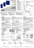


3. Montage
Mounting
Montage
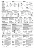
3.4 Wandmontage
Rohrmontage
42,4
( 1 )
( 1 ) Bohrschablone
Einfachthermostat
( 1 ) Länge nach
Bedarf kürzen.
( 2 ) Bohrschablone
Doppelthermostat
( 3 ) Biegeradius
≥
5 mm.
( 4 ) Fühler mit Formfeder gegen
Herausgleiten sichern.
Wall mounting
Pipe mounting
( 1 ) Drilling jig,
( 1 ) Shorten according
to requirements.
single thermostat
Ø
40 - 120 mm
( 2 ) Drilling jig,
dual thermostat
95,4
( 3 ) Bending radius
≥
5 mm.
( 4 ) Shaped spring secures
probe against sliding out
( 3 )
( 1 )
Montage mural
Montage
tuyaterie
( 1 ) Gabarit de perçage
thermostat simple
( 4 )
( 2 )
( 1 ) Raccourcir longueur
suivant besoin.
( 2 ) Gabarit de perçage
thermostat double
( 3 ) Rayon de courbure
≥
5 mm.
( 4 ) Sonde avec ressort de
sécurité pour assurer le
maintien dans la gaine.
T
= 120°C
max
4. Einstellungen / Funktionen
Settings / functions
Réglages / Fonctions
4.1 Sollwerteinstellung TR Begrenzung Regelbereich
Setpoint adjustment TR Control range limiting
4.2 Sollwert- / Grenzwertein-
4.3 Entriegeln STB / STB reset / Déverrouillage STB
stellung
TW/STW/STB
Nach Unterschreiten des
eingestellltenGrenzwertes
um ca. 10% kann der
STB entriegelt werden.
Réglage de consigne TR Limitation de la plage de réglage
Setpoint / limit setting
TW/STW/STB
Réglage seuil/
consigne
TW/STW/STB
The STB can be reset
when the temperature has
fallen about 10% below
the preset limit.
Si la température descend
sous le seuil limite d'env.
10 %, le STB peut être
déverrouillé
4.4 Verhalten bei Bruch des Messsystems 4.5 Verhalten bei Untertemperatur 4.6 Schutzart IP 54
IP54 protection
Schutzart IP 54
4.7 Plombierung
Bei Zerstörung des Messsystems, d.h. wenn die Ausdeh-
nungsflüssigkeit entweicht, fällt der Druck in der Membra-
ne ab und öffnet beim STW und STB bleibend den Strom-
kreis. Beim STB ist ein Entriegeln nicht mehr möglich.
Wird der Fühler beim STW oder STB auf eine
Temperatur unter ca. -20°C abgekühlt öffnet
sich der Stromkreis, schließt sich jedoch bei
Temperaturanstieg wieder selbsttätig.
Zum Erreichen der Schutzart IP 54 To achieve the enclosure protection Pour atteindre l’indice de protection
(Plombe nicht im Lieferumfang)
müssen die Dichtungselemente wie rating IP54, the sealing elements
dargestellt eingelegt sein.
IP 54 les joints doivent être posi-
tionnés comme ci-dessous repré-
sentés.
Lead sealing
must be inserted as shown in the
diagram.
(not included in delivery)
Plomb
Response to measuring system fracture
If the measuring system is destroyed (i.e. the expan-
sion liquid leaks) then the membrane pressure falls and
the circuit will be permanently opened in the case of an
STW or STB. On an STB, resetting is no longer possi-
ble.
Response to low temperature
If the probe temperature on an STB or STW
falls below about -20°C, the circuit will open,
but will automatically close again when the
temperature rises.
(Plombs non fournis)
Comportement en cas de rupture du
système de mesure
Comportement si la températu-
re est trop basse
8
( 1 )
TR:
En cas de destruction du système de mesure, c.-à-d.
lorsque le liquide d’expansion s’échappe, la pression
dans la membrane chute et le circuit électrique reste
ouvert pour STW et STB . Un déverrouillage n’est plus
possible pour STB .
Lorsque la temperature passe sous -20°C
pour STW ou STB, le circuit électrique
s’ouvre, mais se referme automatiquement
lorsque la température remonte.
16
(1) Bohrung beidseitig nur im schraffierten Bereich
(1) Driill only in the cross-hatched area on both sides
(1) Perçage latéral uniquement dans la zone hachu-
rée
STB:
5. Installation
Electrical connection
Raccordement électrique
5.1 Vorschriften und Hinweise
Regulations and notes
Prescriptions et remarques
■
■
Der elektrische Anschluss darf nur von Fachpersonal durchgeführt werden.
Bei der Wahl des Leitungsmaterials, bei der Installation und beim elektrischen
Anschluss des Gerätes sind die Vorschriften der VDE 0100 "Bestimmungen über
das Errichten von Starkstromanlagen mit Nennspannungen unter 1000 V" bzw.
die jeweiligen Landesvorschriften zu beachten.
■
■
The electrical connection must only be made by qualified personnel.
■
■
Le raccordement électrique doit être effectué exclusivement par du personnel qualifié.
Aussi bien pour le choix du matériau des câbles, que pour l’installation ou bien le rac-
cordement électrique de l’appareil, il faut respecter la réglementation en vigueur.
Débrancher les deux conducteurs du réseau lorsque des pièces sous tension peuvent
être touchées lors d’une intervention sur l’appareil.
The choice of cable, the installation and the electrical connection must conform to the
requirements of VDE 0100 “Regulations for the installation of power circuits with nominal
voltages below 1000 V”, or to the appropriate local regulations.
■
■
■
■
If contact with live parts is possible while working on the unit, it must be completely dis-
connected from the supply.
■
■
Das Gerät völlig vom Netz trennen, wenn bei Arbeiten spannungsführende Teile
berührt werden können.
Gerät an der Klemme PE mit dem Schutzleiter erden. Diese Leitung sollte min-
destens den gleichen Querschnitt wie die Versorgungsleitungen aufweisen.
Raccorder l’appareil à la terre sur la borne PE, avec le conducteur de protection. Ce
conducteur doit avoir la même section que les lignes d’alimentation.
Earth the instrument at the PE terminal to the protective conductor. This cable must have a
cross-section that is at least as large as the supply cables.
5.2 Elektrischer Anschluss
Electrical connection
Raccordement électrique
■
■
■
-Kontakt (Steckklemme)
*
geeignet für Anschlussquerschnitt
■
contact (plug-in terminal)
*
suitable for conductor cross-section 0.75 — 2.5 mm2.
■
Contact
(borne à fiche)
*
adapté à une section de fil 0,75 à 2,5mm2 de faible
0,75...2,5mm2 feindrähtig, feindrähtig mit Aderendhülse eindrahtig.
Anschlussverbindung geeignet für fest verlegte Leitungen. Leitungseinführung
mit Zugentlastung. Anbringungsart X bzw. M.
Use core-end ferrule with stranded conductor.
Connection suitable for fixed cabling. Cable entry with strain relief.
Attachment type X or M.
diamètre, faible diamètre avec embout unifilaire.
Raccordement adapté à des câbles fixes. Entrée de câble avec décharge de traction.
Type de fixation X ou M.
■
■
Anschluss gemäß Anschlussbild durchführen.
■
■
Implement the connection according to the wiring diagram.
■
■
Raccordement suivant schéma de raccordement
TR, TW, STW:
STB:
■
Leitungen vorbereiten
/
Anschluss herstellen / Make the connection / Brancher
Anschluss lösen / Disconnection / Débrancher
Prepare the cables / Préparation des câbles
Ø 6-12mm
1
1
2
4
2
4
( 2 ) SW 24 / 24 a/f / OC24
( 1 )
( 2 )
2
4
1
11-13mm
( 1 ) geeignetes Crimpwerkzeug verwenden
( 1 ) Use a suitable crimpng tool
max. 3 mm
(
1
)
U
t
i
l
i
s
e
r
l
’
o
u
t
i
l
d
e
s
e
r
t
i
s
s
a
g
e
a
d
a
p
t
é
®
®
*
„Push-In “-Klemmtechnik: patentierte Anschlusstechnik der Weidmüller GmbH & Co. KG, Detmold
*
“Push-In “ terminal technology is patented by Weidmüller GmbH & Co. KG, Detmold
*Technologie „Push-In®“ : connexion à insertion brevetée par Weidmüller GmbH & Co. KG, Detmold
6. Technische Daten
Technical data
Caractéristiques techniques
zulässige Umge-
bungstemperatur im
Gebrauch
An Fernleitung
und Schaltkopf
Am Temperaturfühler
max. Sollwert +15%
Permissible ambient
temperature
at capillary and switch head
at temperature probe
max. setpoint: +15%
Température ambiante Sur le capillaire et le boîtier
Sur la sonde de
admissible en service
température
max. +50°C
in operation
max. +50°C
+50°C max.
Consigne max. +15%
zulässige
Lagertemperatur
Permissible
storage temperature
Température de stocka-
ge admissible
max. +50°C, min. -30°C
maximum +50°C, minimum -30°C
max. +50°C, min. -30°C
maximale
Schaltleistung
Am Öffnungskontakt
(Kontaktbahn 1-2)
AC 230 V +10%, 16 (2,5) A,
Max.
contact rating
for break contact (SPST-NC)
(contacts 1-2)
230 V AC +10%, 16 (2.5) A,
p.f. = 1 (0.6)
230 V DC +10%, 0.25 A
Pouvoir de coupure
max.
Sur le contact à ouverture
(contacts principaux 1-2)
AC 230 V +10%, 16 (2,5) A,
cos
ϕ
= 1 (0,6)
cos
ϕ
= 1 (0,6)
DC 230 V +10%, 0,25 A
DC 230 V +10%, 0,25 A
Am Schließkontakt
(Kontaktbahn 1-4)
for make contact (SPST-NO)
(contacts 1-4)
Sur le contact à fermeture
(contacts principaux 1-4)
TR, TW, STW: AC 230 V +10%, 6,3 (2,5) A,
TR, TW, STW: 230 V AC +10%, 6.3 (2.5) A,
TR, TW, STW: AC 230 V +10%, 6,3 (2,5) A,
STB: AC 230 V +10%, 2 (0,4) A,
STB: 230 V AC +10%, 2 (0.4) A,
STB: AC 230 V +10%, 2 (0,4) A,
cos
ϕ
= 1(0,6)
p.f. = 1(0.6)
230 V DC +10%, 0.25 A
cos
ϕ
= 1(0,6)
DC 230 V +10%, 0,25 A
DC 230 V +10%, 0,25 A
minimale
Schaltleistung
Zur Gewährleistung einer möglichst großen Schaltsicherheit
wird eine Mindestbelastung von:
AC / DC = 24 V, 100 mA empfohlen
Min.
contact rating
In order to ensure the maximum switching reliability, we recommend a
minimum contact loading of:
AC / DC = 24 V, 100 mA
Pouvoir de coupure
min.
Pour garantir la plus grande sécurité de coupure possible, nous
vous recommandons une charge minimale de :
AC / DC = 24 V, 100 mA
Bemessungsstoßspannung: 2500 V
rated surge voltage: 2500 V
Surtension transitoire de référence : 2500 V
erforderliche
Absicherung
Required
fusing
siehe max. Schaltleistung
see max. contact rating
Fusible nécessaire
Voir pouvoir de coupure maximal
Schaltpunkt-
genauigkeit
bezogen auf den Sollwert bei T +22°C = siehe Typenschildan-
U
gaben am Gerät.
Switching point
accuracy
referred to the setpoint at T +22°C
A
see nameplate data on the instrument
Précision du point de
contact
Par rapport à la consigne pour T +22°C = voir indication de la
U
plaque signalétique
mittlerer
Bei einer Abweichung der Umgebungstemperatur am Schalt-
kopf und der Fernleitung von der Justierumgebungstemperatur
+22°C, entsteht eine Schaltpunktverschiebung.
Höhere Umgebungstemperatur = niedriger Schaltpunkt;
Niedrigere Umgebungstemperatur = höherer Schaltpunkt.
Mean ambient
temperature effect,
referred to setpoint
A deviation of the ambient temperature around the switching head or
the capillary from the calibration temperature of +22°C wil cause a shift
of the switching point.
Higher ambient temperature = lower switching point
Lower ambient temperature = higher switching point
Influence moyenne de
la température
ambiante
En cas de dérive de la température ambiante sur le boîtier et le ca-
pillaire +22°C, il en résulte un déplacement du point de contact.
Température ambiante plus élevée = point de contact plus bas ;
Température ambiante plus basse = point de contact plus haut.
Suivant l’exécution, cette influence est minimisée au moyen d’une
compensation de température.
Umgebungs-
temperatureinfluss
bezogen auf
den Sollwert
Je nach Geräteausführung wird dieser Einfluss durch Einsatz
einer Temperaturkompensation minimiert.
This effect can be minimized by using a temperature compensation,
depending on the instrument configuration.
Gewicht
ca. 0,2 kg
Weight
approx. 0.2 kg
Poids
env. 0,2 kg
Schutzart
EN 60 529 - IP 40 (IP 54). Verschmutzungsgrad 2
Wasser, Öl, Luft, Heissdampf
Enclosure protection
Operating medium
EN 60 529 - IP40 (IP54). Pollution level 2
water, oil, air, superheated steam
Mode de protection
Milieu d’utilisation
Constantes de temps
EN 60 529 - IP 40 (IP 54). Degré de pollution 2
eau, huile, air, vapeur
Betriebsmedium
Zeitkonstante t
0,632
in Wasser
in Öl
≤
≤
≤
45 s
60 s
120 s
Time constant t
0.632
in water
in oil
≤
≤
≤
45 sec
60 sec
120 sec
dans l’eau
dans l’huile
≤
≤
≤
45 s
60 s
120 s
t
0,632
in Luft / Heissdampf
in air/superhtd. steam
dans l’air / vapeur
Wirkungsweise
gemäß DIN EN 60 730-1, DIN EN 60 730-2-9 und DIN EN 14597
TR, TW : Typ 2BL
Mode of operation
as per EN 60 730-1, EN 60 730-2-9 and EN 14597
TR, TW : Type 2BL
Fonctionnement
suivant EN 60 730-1, EN 60 730-2-9 et EN 14597
TR, TW : type 2BL
STW
STB
: Typ 2BKLNP
STW
STB
: Type 2BKLNP
STW
STB
: type 2BKLNP
: Typ 2BFHKLNPV
: Type 2BFHKLNPV
: type 2BFHKLNPV

| General | Details |
|---|---|
| Name | JUMO B 60.3070.0 Surface Mounting Thermostat Room Thermostat Instruction Manual |
| Make | JUMO |
| Language | English |
| Filetype | PDF (Download) |
| File size | 1.9 MB |
 (1 votes, average: 5.00 out of 5)
 Loading...

JUMO exTHERM-AT Explosion-Protected Surface-Mounted Thermostat Instruction Manual


qunda QD-HVAC10W Programmable Thermostat Installation Guide

Danfoss RET1001M – V2 Room Thermostat Installation Guide

AVATTO WT598 1T1 Smart Thermostat

Honeywell TH5000 Series FocusPRO Non-Programmable Digital Thermostat Installation Guide

GENERAL LIFE 300S Smart Thermostat User Manual

ELKO ep TEV-1 Thermostat Owner’s Manual

GENERAL FH100 Floor Heating Thermostat User Guide

Carrier ecobee3 Lite Smart Thermostat User Manual

Honeywell TH8000 Vertical Non Programmable Thermostat Installation Guide

SALUS HTRS-RF Wireless Digital Thermostat Instruction Manual