GLOBAL CEG Series Convector with Thermostat Instruction Manual

OPERATING
MAINTENANCE
INSTRUCTIONS
INSTALLATION
INSTRUCTIONS
INSTRUCTIONS
-
-
-
The heater must be properly installed before it is used.
Turn the power on at the circuit breaker panel.
Electronic thermostat: Set the thermostat temperature at the
wanted room temperature
1- Once a year, remove the front panel and use a vacuum cleaner
to remove the dust accumulation inside the heater and through
openings of the front panel.
CAUTION: Use supply wires suitable for 90 °C (194 °F).
- For bathroom use, the heater must be installed so that
switches and other controls cannot be touched by anyone
in the bath or shower.
INSTALLATION INSTRUCTIONS
Convector “CEG” Series
2- Cleaning should be done while the heater is disconnected from
the main service panel. Wait until the housing and heating
element cool before performing maintenance.
3- Replace the front panel before energizing.
4- Any other servicing should be performed by a qualified
technician.
CONTROL:
SURFACE WALL MOUNTING;
1- Locate approximately the power supply leads behind the
planned location of the heater. Recommended clearance
below heater base to floor is 4 in. (102 mm) minimum.
Allow 4 in. (102 mm) minimum clearance between sides
of heater and any adjacent walls. The leads shall be at the
right of the wall bracket.
Model with built-in electronic thermostat:
The electronic thermostat shall keep the room temperature in a range
of ± 1 °C (± 2 °F) unless the room is not well insulated or the heater
is too or not enough powerful for the room.
WARNING
When using electrical appliances, basic precautions should always be taken
to reduce the risk of fire, electrical shock and injury, including the following.
WARRANTY
Model without control:
2- Lean the bottom of the wall bracket on the floor and mark
with a pencil the height desired (of the heater bottom)
using the wholes with inches written on the side.
3- Secure wall bracket with the 4 screws supplied. The bottom
of the key holes shall be in line with the previous marks.
Triangle mark on horizontal bar is the center of the heater.
Before installing wall support, align center of heater with
support center mark and make sure the heater sides are at
least 4 in. (102 mm) from any adjacent walls.
Maintain room temperature by a line-voltage wall thermostat
approved for residential heating. Even if it is not mandatory, an
electronic thermostat gives better performance than a conventional
thermostat.
Read carefully these instructions before installation, operation of the
heater. Failure to adhere to the instructions could result in fire, electric
shock, serious personal injury, and death or property damage. Review
frequently for continuing safe operation and instruction of future users,
if necessary.
IMPORTANT
1- Read all instructions before installing or using this heater.
2- This heater is hot when in use. To avoid burns, do not let bare skin
touch hot surfaces. Keep combustible materials, like furniture, pillows,
bedding, papers, clothes, and curtains at least 36 in. (915 mm) from the
front of the heater and away from the sides.
3- Extreme caution is necessary when any heater is used by or near
children or invalids and whenever the heater is left operating and
unattended.
4- Do not operate any heater after it malfunctions. Disconnect power
at service panel and have heater inspected by a reputable electrician
before reusing.
4- Untighten wire holder (for Loomex cable) and make
electrical connections by having the heater the nearest
possible to the electrical wire. For BX cable, remove one of
the two knock-outs, install a connector (not furnished) and
have 6 to 8 in. (15 to 20 cm) of free wire and get them out
of the hole of the wire holder in order to make connections
from outside. Do not forget to connect the green wire to
ground wire in order to have a safe grounded heater.
5- Once connections completed, place bottom T slots in the
base part of support, and clip the upper side of the body in
the upper U shape part of the support.
TOP
HAUT
TOP
HAUT
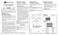
Wiring Diagram:
1
2
INSTRUCTIONS
L1
L2
THERMOSTAT
Model with built-in
L1 Load 1 Load 2 L2
electronic thermostat
8
7
6
5
4
8
7
6
5
4
American version only
up to 240V
Mark
the height
desired
6- Do not let the excess of the supply wire come in contact
with the back of the heater, as well as any other object.
7- Put the main power on.
5- Do not use outdoors.
6- To disconnect heater, turn off power to heater circuit at main disconnect
panel.
Wiring Diagram:
Model without control
CENTRE
CAUTION:
HAUT - TOP
L1
High temperature, risk of fire, keep electrical cords, drapery,
furnishings, and other combustibles at least 36 in. (915 mm)
from the front of the heater and away from the sides. To reduce
the risk of fire, do not store or use gasoline or other flammable
vapors and liquids in the vicinity of the heater.
DETAIL A
7- Do not insert or allow foreign objects to enter any exhaust opening as
this may cause an electric shock or fire, or damage the heater.
8- Do not block air intakes or exhaust in any way whatsoever.
9- This heater has hot and arcing or sparking parts inside. Do not use it in
areas where gasoline, paint, or flammable liquids are used or stored.
10-Use this heater only as described in this manual. Any other use not
recommended by the manufacturer may cause fire, electric shock, or
injury.
11-AMERICAN VERSION ONLY: Some models (up to 240V) include
a visual alarm to warn that parts of the heater are getting excessively
hot. If the light turns on, immediately turn the heater off and inspect
for any objects on or adjacent to the heater that may have blocked
the airflow or otherwise caused high temperatures to have occured.
If no obstruction is visible, the heater must be checked by a quali-
fied person. DO NOT OPERATE THE HEATER WHEN THE
ALARM LIGHT IS ON.
American version only
up to 240V
L2/N
Center mark
3
IMPORTANT
Do not obstruct the front of the heater
for at least 48 in. (1200 mm).
OPTIONS:
All heating equipment and options must be installed in
accordance with local and national codes.
Built-in relay:
4
5
8
8
7
6
5
4
7
6
5
4
A
- Refer to the diagram included with the relay option for
connections.
- Refer to instructions supplied with the option for mounting.
12-The thermostat should not be considered an infallible device in cases
where maintaining a temperature is considered critical. Examples:
Hazardous material storage, computer server room, etc. In these
particular cases, it is imperative to add a monitoring system to avoid
the consequences of a thermostat failure.
4’’
(102 mm)
minimum
4’’
(102 mm)
minimum
4’’ (102 mm)
minimum
INS420-201402-03
SAVE THESE INSTRUCTIONS

| General | Details |
|---|---|
| Name | GLOBAL CEG Series Convector with Thermostat Instruction Manual |
| Make | GLOBAL |
| Language | English |
| Filetype | PDF (Download) |
| File size | 0.27 MB |


GLOBAL WIFI Digital Heating Thermostat User Manual

GLOBAL WiFi Heating Thermostat User Manual

GLOBAL HY09RF WIFI Wireless Thermostat User Manual

GLOBAL Touch Screen Thermostat HY08AC User Manual

GLOBAL Digital Heating Thermostat User Manual

GLOBAL HY06RF-BW/WW/WE Thermostat User Manual


hansgrohe Ecostat 1001 SL Shower Thermostat Instruction Manual

Danfoss TP5001B Programmable Room Thermostat User Guide

Honeywell T6811DP08 Digital Thermostat Instruction Manual

STELPRO SIBTE12C Electronic Thermostat Owner’s Manual

GENERAL 261S RF Digital Room Thermostat Instruction Manual

Danfoss RAE Radiator Thermostat Installation Guide

EMOS P56201UF Floor Heating Thermostat Instruction Manual

nVent RAYCHEM AT-TS-13 Surface Sensing Thermostat Instruction Manual

SALUS Wired Digital Thermostat – Non-programmable HTRS230 User Manual

AVATTO WT598 1T1 Smart Thermostat