Home > Fantini Cosmi > Fantini Cosmi CH121E Flush Mounting Thermostat User Manual
Fantini Cosmi CH121E Flush Mounting Thermostat User Manual


ENG
FLUSH MOUNTING THERMOSTAT, BATTERY OPERATED
INSTALLATION AND USER MANUAL
CH121E istruzioni EN 5680075.indd
1
15/11/2024 12:09:29

| General | Details |
|---|---|
| Name | Fantini Cosmi CH121E Flush Mounting Thermostat User Manual |
| Make | Fantini Cosmi |
| Language | English |
| Filetype | PDF (Download) |
| File size | 0.42 MB |


Fantini Cosmi CH180-230V Touch Screen Programmable Thermostat Instructions

Fantini cosmi C820RQ Dual Power Room Thermostat Instruction Manual

Fantini Cosmi C800WIFI Programmable LED Thermostat Instruction Manual

Fantini Cosmi C820RQ LED Thermostat User Manual

Fantini Cosmi CH141E Battery Operated Weekly Programming Thermostat Owner’s Manual

Fantini Cosmi CH121E Flush Mounting Thermostat User Manual Overview
Summary of Contents
- Page 1: Flush mounting thermostat, battery operated. Installation and user manual.
- Page 2: Intellicomfort CH121E Flush mounting thermostat, battery operated Thank you for purchasing the Fantini Cosmi flush mounting thermostat, model CH121E. This manual contains all the information required for a correct installation and configuration. Carefully read the installation instructions, safety warnings, operating modes and maintenance instructions in this booklet. After removing the packaging, check the integrity of the appliance; if in doubt, do not use it. Installation of the appliance should only be carried out by qualified technicians in compliance with current standards. The use of any electrical appliance involves observing certain basic rules. Do not touch the device with wet hands or wet feet or bare feet. Do not expose the device to the weather (rain, sun, etc.). Before carrying out any maintenance or cleaning work, switch off the power supply. Do not power the appliance with the cover open.
- Page 3: Intellicomfort CH121E Technical features Installation Electrical connections Insertion and replacement of batteries Display and keys description Operation Thermostat configuration Maintenance Disposal Contents of package
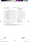
- Page 4: Technical features Power supply: 2 AAA 1.5V batteries Battery duration: approximately 1 year Contact range: 5(3)A 250V~ voltage-free switching Maximum room temperature: T45 °C Temperature adjustment scale: 2 ÷ 40 °C, increase 0.1°C Measurement scale/room T display: -40 ÷ 50 °C Degree of protection: IP20 Compliant with standards: EN 60730-1 and second parts ErP classification: Product not manufactured in Italy
- Page 5: The CH121E thermostat must be installed in a 3-module recessed box, in the middle of the apartment, preferably 1.5 m off the ground. The required components are all included in the package.
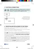
- Page 6: Intellicomfort CH121E Installation and maintenance operations must be carried out with the system's electrical power switched off and by qualified personnel, in compliance with the regulations in force. Perform the following operations: Act on the master switch on the electric panel to cut power to the electrical system. Detach the tabs according to the type of plate when required. Fasten the thermostat to the suitable frame. Mount the cover on the body of the thermostat. Connect the two wires of the boiler to terminals 1-2 of CH121E. Screw the frame onto the box using the provided screws. Mount the plate. Switch the electric system back on.
- Page 7: Intellicomfort CH121E Electrical connections must be carried out with the system's electrical power switched off and by qualified personnel. When CH121E is disconnected, the boiler contact remains in its current position. Insert two AAA 1.5 V alkaline long lasting batteries, paying attention to the marked polarities. The life of the batteries is affected by the type of use and the settings made by the user. When the batteries are low, the symbol of the discharged battery flashes on the display. If the batteries are completely discharged, the thermostat quits working and the display reads PRESS HERE TO REPLACE BATTERIES. To replace the batteries, remove CH121E from its housing by pressing inwards on both sides of the cover. The text Disconnected is displayed for one minute when the thermostat is disconnected. All parameters remain stored while the batteries are being replaced.
- Page 8: Intellicomfort CH121E Display and keys description The thermostat is equipped with 4 keys, the function of which varies depending on the situation. Comfort / TMAX Economy / TMIN Off antifreeze Summer/winter Summer relay ON Winter relay ON Room temperature Celsius / Fahrenheit Operation Summer/winter selection Press both keys simultaneously to select summer (cooling) or winter (heating) mode.
- Page 9: Intellicomfort CH121E Operating mode selection Press to set comfort / TMAX mode Press to set economy / TMIN mode Press to set off antifreeze mode Customise the temperature Economy / TMIN 2 ÷ 40 °C Comfort / TMAX 2 ÷ 40 °C Off antifreeze 0 ÷ 7 °C Antifreeze temperature cannot be set in summer mode.
- Page 10: Choice of back lighting duration You may choose the time during which back lighting remains on: Increase/decrease back lighting duration by pressing specific keys. Press together and keep pressed to change back lighting duration. Options include always off or durations from 1 sec to 10 sec.
- Page 11: Intellicomfort CH121E Thermostat configuration Only qualified personnel may configure the device. Configuring the thermostat allows you to customise the device’s operating parameters. Perform the following steps to access the configuration program. Using a sharp object, press the reset button while holding down the “COMFORT/ECONOMY” button. When the display reads P01, release the “COMFORT/ECONOMY” button. The display represents the configuration parameters by an index: P01, P02…. Press or to scroll the parameter indexes. To exit parameter configuration, press or until the display reads “END”.
- Page 12: Intellicomfort CH121E Display mode options include viewing room temperature or set point. Correction of displayed temperature value can be adjusted from -4°C to +4°C in 0.1°C steps. Winter lower limit set point temperature ranges from 2.0°C to 40.0°C. Winter upper limit set point temperature ranges from 2.0°C to 40.0°C. Summer lower limit set point temperature ranges from 2.0°C to 40.0°C. Summer upper limit set point temperature ranges from 2.0°C to 40.0°C. Differential adjustment can be set from ±0.3°C to ±2.0°C in 0.1°C steps. Temperature scale options include Celsius and Fahrenheit. End parameter configuration and store values. Specific differential adjustment values are suited for different types of plants.
- Page 13: Maintenance Use only a soft and dry cloth to clean the device. Do not use water or other liquid substances. Disposal The symbol of the crossed-out wheeled bin indicates that the product must be collected and disposed of separately from household waste. Batteries and the integrated accumulators may be disposed of together with the product. They will be separated at the recycling facilities. A black bar indicates that the product was placed on the market after August 13th, 2005. Participating in the separate collection of products and batteries contributes to the correct disposal of these materials and therefore avoids possible negative consequences for the environment and human health. For more detailed information on the collection and recycling programs available in your country, contact the local authorities or the sales point where you purchased the product.
- Page 14: Page 14
- Page 15: Page 15
- Page 16: Page 16

neptronic TFC54F3X1 Fan Coil Thermostat Installation Guide

GENERAL LIFE NORA 270S Smart Digital Room Thermostat Instruction Manual

White Rodgers 1F95-1277 Big Blue Universal Thermostat Instruction Manual

EMERSON ST765470 Digital Thermostat User Manual

SunTouch 113901 SunStat ConnectPlus Thermostat User Manual

ENSTO ECO16BT-EX Floor Heating Thermostat User Guide

NEOMITIS PRG7 RF 7 Day Two Channel Programmer with RF Room Thermostat Instruction Manual

DAIKIN DKN510 Wireless VRV Communicating Thermostat Installation Guide

GENERAL LIFE ARUNA HT300S Smart Room Thermostat User Manual

EPH CONTROLS CP4 Programmable RF Thermostat User Manual