
ELKO ep TEV-1 Thermostat Owner’s Manual


Technical parameters
Function
TEV-1
Un
T1
T2
Function:
two-level thermostat
L - N
h
Supply terminals:
Supply voltage:
sensor
failure
h
230 V AC / 50 - 60 Hz
max. 2.5 VA / 0.5 W
Input:
Max. dissipated power
(Un + terminals):
Tolerance of supply voltage:
Measured circuit
Measuring terminals:
Temperature ranges
thermostat 1:
3 W
V1
15 %
red LED
green LED
T - T
orange LED
-20 to +20 °C (-4 °F to +68 °F)
-20 to +20 °C (-4 °F to +68 °F)
3 °C ( 1.5 °C) / (37.4 °F ( 34.7 °F))
thermistor NTC 12 kΩ / 25 °C (77 °F )
red LED flashing
h) hysteresis
thermostat 2:
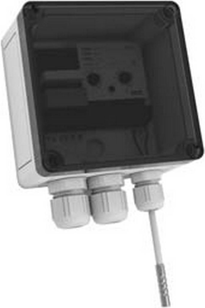
TEV-1 is a double thermostat designated for system of protection of roof watershoots
against freezing. The device is placed in a waterproof box (IP65), sensor with double
insulation, which is a part of the device, senses ambientrature. The device operates
as zonal thermostata with independent setting of upper and bottom operational
temperature. In case the ambient temperature is higher than T1 (upper temperature),
thermostat switches heating of watershoots off (icing melts down). In case the ambient
temperature is lower than T2 (bottom temperature),thermostat also switches heating off
(to big freezing heating cannot manage to melt the ice).
Hysteresis (sensitivity):
Sensor:
Faulty sensor indication:
Accuracy
Accuracy of settings (mech.):
Dependance on temperature:
Output
5 %
< 0.1 % / °C
Number of contacts:
Rated current:
1x changeover / SPDT (AgNi / Silver Alloy)
16 A / AC1
4000 VA / AC1; 384 W / DC
30 A / < 3 s
250 V AC1
Switching output:
Peak current:
Warning
The device is constructed to be connected into 1-phase main and must be installed in
accordance with regulations and norms applicable in a particular country. Installation,
connection and setting can be done only by a person with an adequate electro-technical
qualification which has read and understood this instruction manual and product
functions. The device contains protections against over-voltage peaks and disturbing
elements in the supply main. Too ensure correct function of these protection elements
it is necessary to front-end other protective elements of higher degree (A, B, C) and
screening of disturbances of switched devices (contactors, motors, inductive load etc.) as
it is stated in a standard. Before you start with installation, make sure that the device is
not energized and that the main switch is OFF. Do not install the device to the sources of
excessive electromagnetic disturbances. By correct installation, ensure good air circulation
so the maximal allowed operational temperature is not exceeded in case of permanent
operation and higher ambient temperature. While installing the device use screwdriver
width approx. 2 mm. Keep in mind that this device is fully electronic while installing.
Correct function of the device is also depended on transportation, storing and handling.
In case you notice any signs of damage, deformation, malfunction or missing piece, do
not install this device and claim it at the seller. After operational life treat the product as
electronic waste.
Switched voltage:
Output indication:
Mechanical life:
LED
3x10⁷
Electrical life:
0.7x10⁵
Other information
Operation temperature:
Operation position:
Protection degree:
Overvoltage cathegory:
Pollution level:
-30 to +50 °C (-22 to 122°F)
any
IP65 assembly
III.
2
Max. cable size (mm2):
solid wire 2.5 / with sleeve 1.5 (AWG 12)
110 x 135 x 66 mm (4.33˝x 5.3˝x 2.6˝)
270 g (9.5 oz.)
Dimensions:
Weight:
Standards:
EN 60730-2-9, EN 61010-1
Temperature sensor
TZ-0
Range:
-40°C to +125°C (-40°F to 257°F)
NTC 12K
Scanning element:
Tolerance:
(0.15°C + 0.002|t|)
(τ65) 62 s / 8 s
(τ95) 216 s / 23 s
PVC
In air/ in water:
In air/ in water:
Cable material:
Terminal material:
Protection degree:
Electrical strength:
Insulation resistance:
Length:
stainless steel
IP67
2500 VAC
> 200 MΩ at 500 VDC
110 mm (4.3”)
4.5 g (0.16 oz.)
Weight:
τ65 (95): time, which sensor needs to heat up on 65 (95) % of ambient temperature of
environment, in which is located.
Resistive values of sensors in dependance on temperature
Temperature (°C / °F)
20 / 68
Sensor NTC (kΩ)
14.7
9.8
6.6
4.6
3.2
2.3
30 / 86
40 / 104
50 / 122
60 / 140
70 / 158
Tolerance of sensor NTC 12 kΩ is 5% by 25 °C / 77 °F.
2 / 2

| General | Details |
|---|---|
| Name | ELKO ep TEV-1 Thermostat Owner’s Manual |
| Make | ELKO ep |
| Language | English |
| Filetype | PDF (Download) |
| File size | 1.87 MB |
 (1 votes, average: 5.00 out of 5)
 Loading...

ELKO ep TER-4 Double Thermostat Owner’s Manual

Vtech E-Smart W960 Thermostat Instruction Manual

Wiser CCTFR6100 Radiator Thermostat Instruction Manual

INKBIRD C216T-C226T Plug In Timer Thermostat User Manual

GENERAL Life HT250 Wired Room Thermostat User Guide

Danfoss RAS-C2 Combi Radiator Thermostat Installation Guide

OH-1202H Universal Humidity Touchscreen Thermostat Instruction Manual

PECO TW180 Thermostat Instruction Manual

ENGO CONTROLS SE901WIFI Wireless Internet Wi-Fi Thermostat User Guide

Honeywell VisionPRO Series 7 Day Programmable Thermostat User Guide

Schneider Electric CFMT02ZB Flush-Mounted Thermostat Instruction Manual