
WARMZONE UWG5 WiFi LED Touch Thermostat User Guide

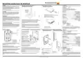


MOUNTING GUIDE/GUÍA DE MONTAJE
CLASSIFICATION
WARNINGS:
1. Mounting of the included sensor /
2. Removing the faceplate
Desmonte la placa frontal
To avoid electric shock, disconnect the heating system power supply
The product is a Class II device (reinforced insulation) and must be connected
to the following leads:
at the main panel before installation and maintenance of the thermostat. Keep thermostat
air vents clean and free from obstruction. This thermostat is an electrical device and must
be installed in compliance with national and/or local electrical codes. Installation must be
performed by qualified personnel where required by law.
Montaje del sensor incluido
•
•
•
•
Phase L1 (L)
Neutral L2 (N)
Max. load 15 A (resistive load)
The Thermostat is to be used with underfloor heating.
120/208/240 V
If a power module with an equipment ground fault protection device (EGFPD) is to be
installed where national and/or local electrical codes require a ground fault circuit interrupter
(GFCI), a separate GFCI must also be installed.
The terminals are suitable for field wiring cables of 12 to 22 AWG.
Heating element in accordance with the supply voltage.
© 2023 OJ Electronics. All rights reserved.
This manual and parts thereof are protected under Danish and international copyright laws.
TECHNICAL DATA
Supply Range............................................................. 120/208/240 Vac 50/60 Hz
Load .............................................................................max. 15 A (resistive load)
Max. power at e.g. ..................................................................1800 W at 120 Vac
................................................................................................3120 W at 208 Vac
................................................................................................3600 W at 240 Vac
a. UWG5 (GFCI).............................................................. Class A (5 mA trip level)
Temperature range ................................................ +5 to +40°C / +41 to +104°F
Amb. temp. range ..................................................... 0 to +25°C / +32 to +77°F
WIFI . ........................................................................................IEEE 802.11 b/g/n
Bluetooth...................................................................version 4.2 (BDR/EDR/BLE)
Contains FCC ID .......................................................................... XPYNINAW106
Contains IC ID .........................................................................8595A-NINAW106
Construction of Control... ..........................................Electronic room thermostat
for regulating electrical underfloor heating.
DISCLAIMER
OJ cannot be held liable for any errors in the material. OJ reserves the right to alter its
products without notice. This also applies to products already on order, provided that such
alterations can be made without requiring subsequent changes in specifications already
agreed. The contents of this material may be subject to copyright and other intellectual
property rights and is either the property of or used under license by OJ Electronics.
Loosen the screw at the bottom
Note! Do not attempt to remove the screw completely.
The OJ trademark is a registered trademark of OJ Electronics A/S.
© 2023 OJ Electronics A/S
ADVERTENCIAS :
Afloje el tornillo en la parte inferior.
¡Nota! no intente retirarlo por completo.
Para evitar descargas eléctricas, desconecte el suministro de alimentación eléctrica del
sistema de calefacción en el panel principal antes de la instalación y el mantenimiento del
termostato. Mantenga limpios y libres de cualquier obstrucciones los orificios de ventilación
de aire del termostato. Este termostato es un dispositivo eléctrico y debe instalarse de con-
formidad con los códigos eléctricos nacionales y/o locales. La instalación debe ser realizada
por personal cualificado donde así lo requiera la ley.
Method of Mounting Control............................................ Independently mounted
control for flush mounting
Type of Action......................................................................................... Type 2.B.
Rated Impulse Voltage ............................................................................... 2500 V
Si se va a instalar un módulo de potencia con un dispositivo de protección de fallo a tierra
del equipo (EGFPD) en un sitio donde los códigos eléctricos nacionales y/o locales requi-
eran el uso de un interruptor de circuito de fallo a tierra (GFCI), se deberá instalar además un
GFCI separado.
The floor sensor is recommended to be placed in a non-conductive
installation pipe, which is embedded in the floor. The pipe must be sealed
at the end and placed as high as possible in the concrete layer.
The floor sensor must be centered in between the heating cable.
The power supply voltage must match the voltage rating of the
heating cable.
© 2021 OJ Electronics. Reservados todos los derechos.
CERTIFICATION
c UL us Listed
UL file number: E157297v
According to the following standards:
Este manual y partes del mismo están protegidas en virtud de las leyes danesas e interna-
cionales sobre derechos de propiedad intelectual
DESCARGO DE RESPONSABILIDAD
OJ no se hace responsable de los errores que pueda contener el material. OJ se reserva el
derecho a realizar cambios en sus productos sin notificación previa. Esto vale también para
los productos ya pedidos, siempre y cuando dichos cambios puedan efectuarse sin nece-
sidad de realizar modificaciones en especificaciones ya acordadas. El contenido de este
material puede estar sujeto a derechos de autor y a otros derechos de propiedad intelectual
y bien es propiedad de OJ Electronics o bien se utiliza bajo la licencia de OJ Electronics.
Thermostat:
UL 60730-2-9
Se recomienda colocar el sensor de piso en un tubo de instalación no
conductor, que se encuentre incrustado en el piso. El tubo deberá estar
sellado en el extremo y colocado lo más elevadamente posible en la capa
de hormigón.
El sensor de piso deberá centrarse entre los cables de calefacción.
La tensión de la alimentación debe coindir con la del cable de calefacción.
CSA E60730-2-9
GFCI:
UL 943 5th ed.
CSA C22.2 No.144.1-16 2nd ed.
e.
Remove the faceplat
This device complies with part 15 of the FCC Rules and ISED Standards. Oper-
ation is subject to the following two conditions: (1) This device may not cause
harmful interference, and (2) this device must accept any interference received,
including interference that may cause undesired operation.
La marca comercial OJ es una marca comercial registrada de OJ Electronics A/S.
© 2021 OJ Electronics A/S
Desmonte la placa frontal.
Patent Pending
3. Wiring / Cableado
4. Sensor connections / Conexiones de los sensores
5. Mounting the thermostat 6. Remount the faceplate
L1 L2
(L) (N)
Clasificación
Montaje del termostato
Remonte la placa frontal
El producto es un dispositivo Clase II (isolation renforcée) y debe ser
conectado a los conductores siguientes:
B S
0 7
Make the sensor connections.
The Floor sensor has no polar-
ity. Connect it to terminals C
and D.
Expansion unit connects to
termianals A and B*
Line L
(Black)
1 2 6
•
•
•
•
Fase L1 (L)
Neutro L2 (N)
120/208/240 V
Carga máxima 15 A (carga resistiva)
El termostato está destinado a ser utilizado con calefacción por suelo radiante.
Line N
(White (120V) or Red (240V)
Los terminales son adecuados para cables de cableado de campo,
calibre 12 a 22 AWG. Elemento calefactor de conformidad con el
voltaje de suministro
3
2
L1(L)
L2(N)
LINE
C D
The floor sensor cable must
120 / 240 VAC
DATOS TÉCNICOS
be routed to the junction box
1800W / 3600W MAX 15A
Rango alimentación eléctrica......................................120/208/240 VCA 50/60 Hz
Carga ........................................................................... máx. 15 A (carga resistiva)
Potencia maxima en el ejemplo .............................................. 1800 W a 120 V CA
................................................................................................ 3120 W a 208 V CA
................................................................................................ 3600 W a 240 V CA
a. UWG4 (GFCI) .................................................. Clase A (nivel de disparo 5 mA)
Rango de temperatura .............................................. +5 a +40 °C / +41 a +104 °F
Rango de temperatura ambiente................................... 0 a +25 °C / +32 a +77 °F
WIFI . ......................................................................................... IEEE 802.11 b/g/n
Bluetooth.................................................................... version 4.2 (BDR/EDR/BLE)
Contiene FCC ID ............................................................................XPYNINAW106
Contiene IC ID ..........................................................................8595A-NINAW106
Construcción del control....................................................Termostato electrónico
ambiente para regular la calefacción eléctrica de piso radiante.
4
1
A B C D
separate
from power wires and the
heating cable cold lead. Ensure
that the
insulation on the electrical wir-
ing and the floor sensor inside
the junctionbox are not damaged.
LOAD
A B
Load - No polarity
Thread the floor sensor cable through the hole in the power base.
Push the electrical wires to the back of the electrical box.
Turn power source OFF at breaker panel. Connect power supply wires to line
side and heating cable wiring to load side of power base.
AWG between 12 - 20.
*Refer to instructions included with expansion unit.
Método de montaje de control.................................................... Control instalado
independientemente para montaje a ras
Tipo de acción......................................................................................... Tipo 2.B.
Voltaje nominal de impulso ........................................................................ 2500 V
Efectúe las conexiones del sensor.
El sensor de piso no tiene polaridad.
Conéctelo a terminales A y B*
Note! Do not detach the screws from the terminal.
When fastening the screws use a torque between 0.8 - 1.2 Nm / 0.6 - 0.9 lbf-ft.
Ensure that the power supplied matches the voltage of the cable kit.
CERTIFICACIÓN
En lista de para c UL us
Número de archivo UL: E157297
De conformidad con las normativas siguientes.
El cable del sensor de piso debe tenderse hasta la caja de
conexiones eléctricas en un conducto separado de los demás cables eléctri-
cos y del conductor frío del cable de calefacción. Asegúrese de que el aisla-
miento del cableado eléctrico y del sensor de piso en la caja de conexiones
no esté dañado.
Pase el cable de sensor de piso a través del orificio en la base de aliment-
ación eléctrica.
Empuje los cables eléctricos hacia la parte trasera de la caja eléctrica.
Install the power base into the electrical
box.
Secure the power base to the wall.
Apague la fuente de alimentación eléctrica en el panel de disyuntores. Conecte
el cableado de la fuente de alimentación al lado de línea y el cableado de la
calefacción al lado de carga de la base de alimentación eléctrica.
AWG entre 12-20.
Termostato :
UL 60730-2-9
CSA E60730-2-9
GFCI:
UL 943 5th ed.
CSA C22.2 No. 144.1-16, 2th ed.
ew
Fasten the scr
Instale la base de alimentación eléc-
trica en la caja eléctrica.
Fije la base de alimentación eléctrica
a la pared.
¡Nota! No separe los tornillos completamente del terminal.
Al apretar los tornillos utilice un par entre 0,8 y 1,2 Nm / 0.6 - 0.9 lbf-pi.
Asegúrese de que la potencia suministrada coincide con la tensión del kit de
cables.
Este dispositivo cumple con la sección 15 de las normas de la FCC y con las nor-
mas ISED. El funcionamiento está sujeto a las dos siguientes condiciones: (1) este
dispositivo no puede ocasionar interferencias dañinas, y (2) este dispositivo debe
aceptar cualquier interferencia recibida, incluso aquellas que puedan ocasionar un
funcionamiento no deseado.
Apriete el tornillo.
*Consulte las instrucciones incluidas con la unidad de expansión.
Pendiente en trámite.
Warmzone Premier Radiant Heating 888.488.9276

| General | Details |
|---|---|
| Name | WARMZONE UWG5 WiFi LED Touch Thermostat User Guide |
| Make | WARMZONE |
| Language | English |
| Filetype | PDF (Download) |
| File size | 0.23 MB |
 (1 votes, average: 5.00 out of 5)
 Loading...

WARMZONE UWG5 Wi-Fi LED Touch Thermostat User Guide

WARMZONE LED WiFi Floor Heating Thermostat Owner’s Manual

WARMZONE BR1015A07 WZ Touch Thermostat User Guide


ENGO CONTROLS SE901WIFI Wireless Internet Wi-Fi Thermostat User Guide

KONIGHAUS Remote Infrared Heater Plus Thermostat User Guide

Eurotronic Technology sprit Z-Wave Smart Radiator Thermostat Installation Guide

INKBIRD ITC-306A Digital Thermostat User Manual

NT NetX X5N-SM Thermostat Installation Guide

Gelia ip24 1.5m Cable With Stepless Thermostat Instruction Manual

GENERAL LIFE SENNA 300S Digital Room Thermostat User Manual

EUROLAMP HY06BW Digital Heating Smart Thermostat User Manual

DEVI 316 Electronic Thermostat Installation Guide

Fantini Cosmi C800WIFI Programmable LED Thermostat Instruction Manual