VIVE TP-N-751 Programmable Thermostat Installation Guide

Installation Manual
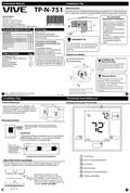
Installation Tips
Wall Locations
TP-N-751
The thermostat should be installed approximately 4 to 5 feet above the
floor. Select an area with average temperature and good air circulation.
Vive Comfort
P.O. Box 3377
Springfield, MO 65808-3377
Do not install
thermostat in locations:
• Close to hot or cold air ducts
• That are in direct sunlight
• With an outside wall behind
the thermostat
• In areas that do not require
conditioning
• Where there are dead spots
or drafts
(in corners or behind doors)
Toll Free : 888-776-1427
Hours of Operation: M-F 9AM - 6PM Eastern
VM-751-IM-2422
*VM-751-IM-2422*
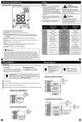
Power Type
Thermostat Application Guide
Battery Power
Description
Hardwire (Common Wire)
Hardwire (Common Wire) with
Battery Backup
Gas or Oil Heat
Yes
Yes
Yes
Yes
Electric Furnace
• Where there might be
concealed chimneys or
pipes
Heat Pump (No Aux. or Emergency Heat)
Heat Pump (With Aux. or Emergency Heat)
Multi-Stage Systems
Installation Tip
A trained, experienced
technician must install this
product.
Yes
Yes
Pick an installation location that is easy for
Heat Only Systems
the user to access. The temperature of the
location should be representative of the
building.
Cool Only Systems
Yes
Yes
Carefully read these
instructions. You could damage
this product or cause a
Millivolt
hazardous condition if you fail to
follow these instructions.
Table of Contents
Page
Subbase Installation
Installation Tips
Thermostat Quick Reference
Wiring
Wiring Diagrams
Technician Setup
Specifications
2-3
4-5
6
7-9
10-15
16
Horizontal Mount
Vertical Mount
Una version en español de este
manual se puede descargar en
la pagina web de la compañia.
Installation Tip:
Electrical Hazard
Failure to disconnect the power before
beginning to install this product can
cause electrical shock or equipment
damage.
Mercury Notice
All of our products are mercury free.
However, if the product you are
replacing contains mercury, dispose of
it properly. Your local waste
management authority can give you
instructions on recycling and proper
disposal.
For vertical mount put one screw on the top
and one screw on the bottom.
For horizontal mount put one screw on the
left and one screw on the right.
U.S. Registered Trademark. Patents pending
Copyright 2024 All Rights Reserved.
1
2
Rev. 2422
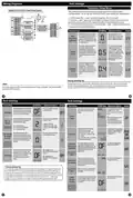
Installation Tips
Thermostat Quick Reference
Mount Thermostat
Getting to know your thermostat
Align the 4 tabs on the subbase with
corresponding slots on the back of the
thermostat, then push gently until the
thermostat snaps in place.
Battery Installation
Battery installation is optional if thermostat is
hardwired (R and C terminal connected to 24V
power).
Important:
High quality alkaline batteries are recommended.
Rechargeable batteries or low quality batteries
do not guarantee a 1-year life span.
Insert 2 AA
Alkaline batteries
(included). High
quality alkaline
batteries are
recommended.
LCD Display
Located on the back of the thermostat.
Glow in the dark light button
About The Private Label Badge
All of our thermostats use the same universal magnetic badge. Visit the
company website to learn more about our free private label program.
Fan Button
System Button
Temperature Setpoint Buttons
Private Label Badge
Gently slide a screwdriver into the
bottom edge of the badge. Gently turn
the screwdriver counter clockwise. The
Use the bevel on lower ridge
badge is held on by a magnet in the well
of the battery door. The badge should pry
off easily. DO NOT USE FORCE.
Magnet in door
4

| General | Details |
|---|---|
| Name | VIVE TP-N-751 Programmable Thermostat Installation Guide |
| Make | Vive |
| Language | English |
| Filetype | PDF (Download) |
| File size | 0.27 MB |


VIVE TP-S-955WH Programmable Thermostat Instruction Manual

VIVE TP-S-855C Digital Programmable Thermostat Instruction Manual

VIVE TP-N-751 Programmable Thermostat Installation Guide Overview
Summary of Contents
- Page 1: Installation tips include selecting a location approximately 4 to 5 feet above the floor with average temperature and good air circulation. Do not install the thermostat close to hot or cold air ducts, in direct sunlight, with an outside wall behind it, in areas that do not require conditioning, or where there are dead spots or drafts. A trained, experienced technician must install this product, and the installation location should be easily accessible for the user. Carefully read the instructions to avoid damaging the product or causing hazardous conditions. Electrical hazard: Disconnect the power before beginning installation to prevent electrical shock or equipment damage. All products are mercury-free, but if replacing a mercury-containing product, dispose of it properly. For vertical mount, use one screw on the top and one on the bottom; for horizontal mount, use one screw on the left and one on the right. Battery installation is optional if the thermostat is hardwired, and high-quality alkaline batteries are recommended for optimal performance. The LCD display is located on the back of the thermostat, and the glow-in-the-dark light button is included. The private label badge can be removed by gently sliding a screwdriver into the bottom edge and turning it counterclockwise.
- Page 2: Thermostat quick reference Getting to know your thermostat Caution: Electrical hazard If you are replacing a thermostat, make note of the terminal connections on the thermostat that is being replaced. Failure to disconnect the power before beginning to install this product can cause electrical shock or equipment damage. Warning: All components of the control system and the thermostat installation must conform to Class II circuits per the NEC Code. The low battery indicator is displayed when the AA battery power is low. If the user fails to replace the battery within 21 days, the screen will only show the low battery indicator but maintain all functionality. Max torque = 6in-lbs. Do not overtighten terminal block screws, as this can damage the terminal block. This thermostat is hardwire powered when the 24V transformer is connected to the Common and RC terminals of the thermostat.
- Page 3: Wiring Diagrams Tech Settings Technician Setup Menu This thermostat has a technician setup menu for easy installer configuration. To set up the thermostat for your particular application, hold down the + and - buttons together for 3 seconds. Use the + and - buttons to modify a setting. The swing setting, often called “cycle rate,” is adjustable. Temperature swing can be customized for this individual application. This setting allows the thermostat to operate a PTAC. This setting allows you to select the number of heat and cool stages. Use the buttons to select ON/OFF for PTAC mode. This setting allows the system to run Gas, Oil, Propane, or any other types of auxiliary heat. When turned on, the thermostat will operate a heat pump.
- Page 4: Tech settings LCD will show adjustment options. This feature allows you to set a delay. Set a maximum heating setpoint limit. The setpoint temperature cannot be raised above this value. This feature allows you to set a minimum cooling setpoint limit. The compressor will run for at least the selected time before turning off. The display light can be configured to stay on all the time or turn on when any key is pressed. The cooling fan delay setting will delay the fan from coming on in cool mode. The display range of temperature is 41˚F to 95˚F (5˚C to 35˚C). Your new thermostat has a 5 year limited warranty.

CLIMATE MASTER CXM2 Communicating Awc Thermostat Installation Guide

telethings teleRelays-2L Device Thermostat User Manual

Honeywell Home ElitePRO S1200 Smart Thermostat User Guide

SECURE radbot 1 Intelligent Radiator Thermostat Instruction Manual

SALUS CONTROLS IT800WIFI Smart Thermostat Installation Guide

GENERAL HT220 RF Digital Room Thermostat User Manual

hansgrohe 15763003 Shower Select Thermostat Instruction Manual

EPH CONTROLS CDT2-24 Room Thermostat Instruction Manual

ENGO CONTROLS E25-BATW Zig Bee 868MHz Smart Thermostat User Guide

Danfoss CET B-RF Wireless Electronic Hot Water Cylinder Thermostat Installation Guide