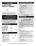
LUXPRO PSD111+ Series Thermostat Instruction Manual
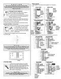

WIRING DIAGRAMS
C A U T I O N
Read instructions carefully before removing any wiring from existing
thermostat. Wires must be labeled before they are removed. When removing
wires from their terminals, ignore the color of the wires since they may not
comply with any standard.
These diagrams are provided for new installations or un-referenced
wires.
HEATING SYSTEMS
COOLING SYSTEMS
W
H
V
4
5
*RH-RC
shorted
W
W
RH RC
R
RH
RH
via jumper
selection
*RH-RC
shorted
via jumper
selection
B
O
B
O
REMOVING THE OLD THERMOSTAT
1. Switch electricity to the furnace and air conditioner
OFF; then proceed with the following steps.
Y
W
R
Y
G
RC
C*
V
F
RC
Y
RC
Y
6
G
F
2. Remove cover from old thermostat. Most are snap-on
types and simply pull off. Some have locking screws on
the side. These must be loosened.
G
G
C
TC
B
C
B
TC
OPTIONAL
OPTIONAL
C
C
ALL COMMON WIRES ARE OPTIONAL
AND MAY BE TAPED OFF
ALL COMMON WIRES ARE OPTIONAL
AND MAY BE TAPED OFF
* IF Y AND "C" ARE BOTH PRESENT,
"C" IS THE COMMON WIRE
3. Note the letters printed near the terminals. Attach labels (enclosed) to
each wire for identification. Label and remove wires one at a time. Make
sure the wires do not fall back inside the wall.
HEATING / COOLING SYSTEMS
4- or 5-WIRE WITH ONE TRANSFORMER
HEATING / COOLING SYSTEMS
5- or 6-WIRE WITH TWO TRANSFORMERS
W
H
V
4
5
W
H
V
4
5
W
W
4. Loosen all screws on the old thermostat and remove it from the wall.
RH RC
B**
O
R
RH
B**
O
RH
RH
DO NOT CONNECT
A "B" WIRE HERE
DO NOT CONNECT
A "B" WIRE HERE
UNLESS YOU ARE SURE
THAT IT IS CORRECT
R
E
M
O
V
E
J
U
M
P
E
MOUNTING THE PSD111+ ON THE WALL
UNLESS YOU ARE SURE
THAT IT IS CORRECT
B
O
B
O
1. Decide whether the thermostat will be mounted vertically or horizontally.
OPTIONAL
OPTIONAL
R
D
RC
Y
R
*RHxRC
RC
Y
RC
Y
2. Strip insulation 3/8 in. (9.5mm) from
Y
G
C*
6
C*
6
not shorted
via jumper
selection
W
wire ends and clean off any corrosion.
R
F
G
F
G
G
3. Fill wall opening with non-combustible
insulation to prevent drafts from affecting
the thermostat.
C
B
TC
C
B
TC
OPTIONAL
OPTIONAL
C
C
*RH-RC
shorted
ALL COMMON WIRES ARE OPTIONAL
AND MAY BE TAPED OFF
* IF Y AND "C" ARE BOTH PRESENT,
"C" IS THE COMMON WIRE
** IF A "B" WIRE IN YOUR SYSTEM IS A
ALL COMMON WIRES ARE OPTIONAL
AND MAY BE TAPED OFF
* IF Y AND "C" ARE BOTH PRESENT,
"C" IS THE COMMON WIRE
** IF A "B" WIRE IN YOUR SYSTEM IS A
via jumper
selection
SYSTEM COMMON, THEN CONNECTING IT
AT THE "B" TERMINAL MAY CAUSE
DAMAGE TO YOUR SYSTEM
SYSTEM COMMON, THEN CONNECTING IT
AT THE "B" TERMINAL MAY CAUSE
DAMAGE TO YOUR SYSTEM
4. Grip the device per the diagram below to remove the front plate
from the back plate.
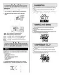
TYPICAL 2 WIRE HEAT HOOKUP
24 VAC AND MILLIVOLT SYSTEMS
TYPICAL 3 WIRE HEAT HOOKUP
WHERE THIRD WIRE IS FAN WIRE
GAS
VALVE
GAS
VALVE
W
W
AC
LINE
AC
LINE
RH
XFMR
24
RH
XFMR
24
VAC
VAC
B
B
*RH-RC
shorted
via jumper
selection
O
O
*RH-RC shorted via
jumper selection
RC
RC
Y
Y
G
C
N
O
T E
G
FAN
If you are mounting the base to a soft material like plasterboard or if you
are using the old mounting holes, the screws may not hold. Drill a 3/16-
in. (4.8mm) hole at each screw location, and insert the plastic anchors
provided. Then mount the base as described below.
C
OPTIONAL
COMMON
OPTIONAL
COMMON
TYPICAL 4 WIRE HOOKUP
HEATING AND COOLING
GAS
VALVE
W
AC
LINE
RH
XFMR
24
VAC
B
O
*RH-RC shorted via
jumper selection
RC
Y
COOL
COMPRESSOR
G
FAN
C
OPTIONAL
COMMON
TYPICAL 5 WIRE HOOKUP
HEATING AND COOLING
TYPICAL SINGLE STAGE HEAT PUMP
HEATING AND COOLING
ATTACHING WIRES
5. Route the wires through the large hole in the base
plate by the terminal block. Hold the base against the
wall, with the wires coming through. Position the base for
best appearance (to hide any marks from an old
thermostat). The terminal block should be either to the
right of or below the routing hole. Attach the base to the
wall with the two screws provided.
USE "B" OR "O"
BUT NOT BOTH
GAS
VALVE
W
W
AC
LINE
RH
RH
XFMR
24
VAC
*RH-RC
shorted
via jumper
selection
B
OR
B
O
B
O
CHANGEOVER
VALVE
O
24
VAC
24
VAC
AC
LINE
AC
LINE
RC
Y
RC
Y
XFMR
XFMR
HEAT
COMPRESSOR
COOL
COMPRESSOR
G
G
FAN
FAN
N O T E
C
C
OPTIONAL
COMMON
OPTIONAL
COMMON
Install two AA batteries in the unit regardless if the the C wire is
connected to 24VAC. This will ensure that all MENU settings will be
preserved during a power outage condition.
NOTE: ADD JUMPER BETWEEN "W" AND "Y"
*RHxRC
not shorted
via jumper
selection
| General | Details |
|---|---|
| Name | LUXPRO PSD111+ Series Thermostat Instruction Manual |
| Make | LUXPRO |
| Language | English |
| Filetype | PDF (Download) |
| File size | 0.25 MB |


LuxPro T10-1141 Heat Thermostat Instruction Manual

LuxPro PSPLV512d Programmable Heating Thermostat Instruction Manual


aube Electronic Thermostat TH131 Owner’s Manual

EUROTRONIC Spirit ZigBee Energy Saving Radiator Thermostat User Guide

Braeburn Programmable Touchscreen Thermostat User Manual

GENERAL SENNA 270S Smart Room Thermostat User Manual

SALUS iT500 Internet Thermostat Installation Guide

Haswill Electronics STC-8080H Thermostat User Guide

GENERAL LIFE MITRA 220 Digital Room Thermostat User Manual

eurotronic Comet Zigbee Energy Saving Radiator Thermostat Instruction Manual

meross T6R Wireless Smart Thermostat User Manual

sinope Smart Floor Heating Thermostat TH1310WF Installation Guide