HBX THM-0500 Touch Screen Programmable Thermostat Instruction Manual


Installation Manual
THM-0500 Touch Screen Programmable Thermostat
Version 1.04
THM-0500
HBX Control Systems Inc.

| General | Details |
|---|---|
| Name | HBX THM-0500 Touch Screen Programmable Thermostat Instruction Manual |
| Make | HBX |
| Language | English |
| Filetype | PDF (Download) |
| File size | 0.52 MB |


HBX THM-0100 Programmable Thermostat Instruction Manual

HBX THM-0500 Touch Screen Programmable Thermostat Instruction Manual Overview
Summary of Contents
- Page 1: Installation manual for the THM-0500 touch screen programmable thermostat. Version 1.04 of the THM-0500. Produced by HBX Control Systems Inc.
- Page 2: Introduction This manual will help with the installation, parameter setting, troubleshooting, and general maintenance requirements for the controller. To guarantee the safe and reliable operation of this control, you must first read this manual in detail and take particular note of any and all warnings or caution directives prior to connecting to AC power. Only suitably qualified individuals with formal training in electrical and HVAC controls should attempt the installation of this equipment. Incorrect wiring and installation will affect the warranty provided with this unit. Wiring must be completed in accordance with the codes and practices applicable to the jurisdiction for the actual installation. The HBX THM-0500 is a microprocessor based controller and as such is not to be regarded as a safety (limit) control. Please consult and install the heating or cooling appliance in accordance with the manufacturer’s recommendations. Safety symbols and warnings Refer to the specified electrical or mechanical drawing at the back of the manual. A measure taken in advance to prevent dangerous or an unpleasant event.
- Page 3: Receipt & inspection After receiving, inspect the unit for any possible physical damage that may have occurred during transportation. After unpacking the unit make sure the box contains: 1 x Universal sensor, 1 x Thermostat THM-0500, 1 x Thermostat Wall Cutout Template, Instruction Manual. Description The THM-0500 is a programmable thermostat designed to be used with the ZON-0550 Zone Control, optional Wi-Fi™ ThermoLinx™ Module, and HBX Zone mobile app. The thermostat has four daily, automatic settings (wake, day, evening, sleep) and weekend settings. It is normal for the THM-0500 screen to remain off up to 120 seconds upon start-up. The THM-0500 has two external sensor inputs, multiple heating/cooling modes and can function as a digital setpoint/aquastat. Some features of the THM-0500 are: dual stage heating or cooling, P.I.D. algorithm, large, full colour touch screen display, user-friendly programming features, includes external sensor. Technical data and dimensions Input power: 5VDC 120mA. Dimensions: 80 x 110 x 26mm. ETL Listings: Only used with ZON-0550. Storage: +10C to +40C. Languages: English.
- Page 4: Programming THM-0500 Navigating the thermostat The touchscreen of this thermostat makes it easy to change used settings. Simply touch the temperature to adjust your desired target temperature. Pressing the menu icon on the top right corner allows you to view the main “Setup Menu” options. Pressing the back icon allows you to return to the home screen or setup menu. Touching the area below the current temperature allows you to see what current demands are present. How to set target temperature How to see current demand Current demands include fancoil heat.
- Page 5: Setting the thermostat involves accessing the Special Functions screen by holding the menu icon for 5 seconds. The heat only function is for applications using a single heating source. The cool only function is for applications using a single cooling source. The heat and cool function is for applications using both a single heating and a single cooling source. The 2 stage heat function is for applications using 2 stage heating. Users can select between heating, cooling, and various combined modes. Options can be adjusted by simply touching any item on the screen. Additional settings include backlight, room offset, and setbacks. Geo mode is also available for different functions. Each function has specific settings to customize the thermostat's operation.
- Page 6: Functions 2 stage cool function is for applications using 2 stage cooling. 2 heat with cool function is for applications using 2 stage heating and 1 stage cooling. 2 cool with heat function is for applications using 2 stage cooling and 1 stage heating. 2 heat and 2 cool function is for applications using 2 stage heating and 2 stage cooling. This option is only available in Geo Mode. You must set Geo mode to enable this function. This option allows you to dim the idle mode screen to a darker setting.
- Page 7: View Auto allows you to choose between automatic changeover or manual changeover. Changeover refers to the thermostat being switched from heat to cool as the air crosses a certain temperature. Auto changeover switches from heat to cool automatically while manual changeover thermostats must be changed by hand. Room Offset allows you to program an offset if the thermostat is not reading the same temperature as the actual temperature in the room. You can put an offset of -1 °F to match the temperatures. Setbacks allows you to program a setback to maximize energy during time frames where the zone may be vacant. You can program up to 4 setbacks when selecting time periods in the schedules menu. Geo Mode allows you to control 2 or 4 pipe systems for geothermal applications. This mode can only be turned on/off using the first THM-0500 thermostat connected to the ZON-0550 Controller. Default is a 2 pipe system; to change to a 4 pipe system, go to zone setup options.
- Page 8: Setup Menu allows you to view the main options. Pressing the back icon returns you to the home screen or setup menu. To select an option, touch any item to adjust its setting. Schedule options can be accessed by touching schedule on the display. Weekday programs allow adjustment of four time periods. The back option returns to the previous screen. There must be a minimum of 2°F differential between hot and cold settings. Cooling must be a minimum of 2°F higher than heating. Weekend programs also allow adjustment of four time periods. A cooling setpoint is available when the thermostat has any cooling function.
- Page 9: Schedules Set the temperature for when the zone is in Away Mode. Away Mode can only be set on the thermostat if setbacks are enabled in the System Function screen options. Away mode will override the schedule to a lower/higher temperature. When Setbacks are set, use this to change the minimum/maximum temperature for your zone depending on if your zone is set up for heating or cooling. If the temperature in the zone falls below/rises above this temperature, heating or cooling will come on. Change the minimum temperature for your zone. If the temperature in the zone falls below this temperature, heating will come on. Change the maximum temperature for your zone. If the temperature in the zone increases above this temperature, cooling will come on. This setting only applies to heating/cooling modes.
- Page 10: Changeover Setup menu Auto: this option allows you to change automatically from heat mode to cool mode or vice versa Heat: allows the user to be only in heat mode Cool: allows the user to be only in cool mode System setup Time: this option is only available when you select “YES” in view auto options in the special functions screen Applicable to: heat/cool, 2heat/cool, 2cool/heat and 2heat/2cool modes This option allows you to select between room, floor and dual sensor modes If you are setting your thermostat as a DHW zone, see zone demand on page 9 If you are using an external room thermistor, see page 13 for thermistor switch settings
- Page 11: Dual mode option allows for temperature feedback from both air and floor sensors. The thermostat will not allow the floor temperature to exceed the maximum value to protect the floor covering. The thermostat will not allow the floor temperature to drop below the minimum value to protect the floor covering. In a two-stage heating mode, only the radiant heating contact is turned off. The floor maximum and minimum settings are adjustable. Sensor 1 is automatically set to the floor sensor. Mode setup is essential for configuring dual mode settings. The maximum floor temperature is set to 80°F. The minimum floor temperature is set to 70°F. The dual mode setup is crucial for maintaining optimal floor temperature.
- Page 12: Floor mode allows the thermostat to operate based on floor temperature only. The differential option in floor mode helps reduce short cycling by setting a range around the target temperature. A differential of 4°F means the temperature can vary 2°F above and below the setpoint. The floor mode sensor is automatically set to the floor sensor. Access to the system setup menu is available through the setup options. Changeover mode can be set to automatic. The setup menu includes scheduling options. Floor mode is only available when heating modes are the primary function. Sensor temperature provides feedback from the floor surface to the thermostat. The maximum floor temperature can be set for sensor 1.
- Page 13: Zone Setup options This setting takes you to the Zone Setup Menu. This option allows the user to set the zone module sequence order. Adjusting the sequence order can only be done using the first THM-0500 thermostat connected to the zone module. Selecting sequence order (1-4) will set the zone module as the “master”. This option allows the user to determine what happens when the thermostat makes a call. Demand options include low temperature demand, high temperature demand, domestic hot water, and fancoil demand. This option allows the user to set a priority on a zone(s) over other zone(s). Priorities range from 1 (highest) to 7 (lowest). Higher priorities will lock out lower priorities until the demand has been satisfied. The Priority Shield option allows a zone to ignore other priorities from other zones.
- Page 14: Zone Setup This option allows the user to see the password to connect to the HBX Zone App. Selecting this option allows you to change the password. With this option, if the thermostat is connected to the first zone module it will display the master ID. If selected it will put the module into “Discovery mode.” If the thermostat is connected to additional zone modules, it will indicate the ID of the master module it is paired to. This option allows you to set the zone as a damper zone. 2 zones and 2 dampers can be set up per zone module. THM-0500 thermostats must be only wired in THM1 and THM3 terminals when using dampers. This option allows you to control a 4 pipe system in a geothermal application. This setting takes you to the Fancoil Setup Menu.
- Page 15: Fancoil setup includes several options for fan operation. The fan on demand option activates the fan with any fancoil demand. Zone on demand turns the zone pump on with any fancoil demand. Temperature averaging averages the temperature between thermostats to control heating or cooling. Fan mode settings include off, on, and intermittent operation. The intermittent fan setting allows for specific on/off times for the fan. The fan can be set to operate for a defined duration, applicable only when in intermittent mode. Fan operation can be customized based on user preferences for heating and cooling. Each setting impacts how the fancoil responds to temperature changes. Proper configuration of these settings ensures efficient climate control.
- Page 16: Fancoil Setup Fan on demand Fancoil Mode INT: Intermittent Fan Off Sets the amount of time that must pass before the fan can come on again. System Setup This option will change the thermostat temperature to either Celsius or Fahrenheit. Stage Delay Use this setting to adjust the lag time between stage 1 and stage 2 coming on. This option is only available in 2 stage applications. Sync Code This number is the identifier used in the HBX Zoning App to connect to your thermostat.
- Page 17: Setup menu allows access to the system setup menu. Set the time for your appropriate time zone. Set the current day of the week. Set the appropriate time zone for your area. Use this setting to allow the network to automatically update your time when WiFi is enabled on your system. Changeover mode is set to auto. Time setup includes options for time, day of week, and time zone. Current time is displayed as 10:00 am. Current day of the week is Tuesday. Time zone is set to Central.
- Page 18: Installation and wiring Mounting instructions It is important to identify the ideal location of the thermostat for proper room temperature. The thermostat should be approximately 5 feet from the floor and at least 1 foot from door openings on an interior wall. Avoid exposing the thermostat to direct sunlight, air flows, and heat sources. Use a screwdriver to gently pop the front cover off from the top of the thermostat to expose wiring terminals. Do not use the screwdriver on the bottom of the thermostat to avoid damage. On the THM-0500, the room thermistor switch is located on the bottom left corner of the thermostat. Toggling this switch allows the user to alternate between the built-in room thermistor or an external room thermistor connected to pins 1 and 2 on the THM-0500.
- Page 19: Wiring examples for THM-0500 using internal sensor. THM-0500 using DHW sensor as a digital aquastat. THM-0500 using room sensor. THM-0500 room averaging using 2 external room sensors. To use external room thermistor, toggle dispswitch from internal to external on THM-0500. Sensor input can be used for DHW, room, floor, and outdoor sensors. Do not connect power here. To ZON-0550. INT. ROOM. EXT. ROOM.
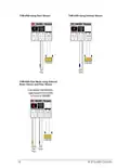
- Page 20: THM-0500 using Floor Sensor THM-0500 using Outdoor Sensor To use external room thermistor, toggle dispswitch from Internal to External on THM-0500 DO NOT CONNECT POWER HERE THM-0500 Dual Mode using External Room Sensor and Floor Sensor External Room Sensor Floor Sensor INT. ROOM EXT. ROOM To ZON-0550
- Page 21: Troubleshooting guide Blank screen - Check the ZON-0550 power. - Check wiring polarity between the THM-0300/THM-0500 and ZON-0550 module. - Ensure zones 1 and 3 damper/4-pipe is set correctly. Stage 2 won’t come on - Check stage delay in system setup for proper time. - In special functions ensure you have selected correct thermostat type. Demand not coming on - Demands may take up to 5 minutes to operate due to P.I.D algorithm. - Verify wiring on the ZON-0550 module. - Check priorities settings in zone setup. - Check the changeover settings. Temperature not displaying correct value - If it is showing dash lines ensure that the proper thermostat mode is selected in mode setup. - Ensure external sensor(s) is wired correctly. - Make sure the external room dipswitch on the board is in the correct position. Target changing - Check the setback schedule. - If you’re in auto changeover, then the target can change to either heating target or cooling target based on actual room temperature.
- Page 22: Troubleshooting guide Issue Possible causes & resolutions Thermostat(s) not showing up on HBX Zone App - Verify sync code and password on thermostat is correct when adding devices - Manually check in thermostat(s) - Ensure zone modules are paired Thermostat settings not displayed on the HBX Zone App - Contact HBX Technical support for contactor code to unlock advanced settings.
- Page 23: Limited warranty HBX Controls warrants each of its products to be free from defects in workmanship and materials under normal use and service for a period of 24 months from date of manufacture or 12 months from date of purchase. If the product proves to be defective within the applicable warranty period, HBX will repair or replace said product at its discretion. Replacement product may be new or refurbished of equivalent or better specifications. Warranty service may be obtained by contacting your nearest HBX Controls office via the original Authorized Agent. Proof of purchase must be provided to expedite the issuance of a Factory RMA. The defective product must be packaged securely for return, with the RMA number visible on the outside of the package. HBX reserves the right to charge a reasonable levy for costs incurred, in addition to mailing or shipping costs. The purchaser's sole remedy for a defective product shall be repair or replacement. HBX shall not be liable under this warranty if the defect was caused by misuse, neglect, or other causes beyond intended use. This limited warranty statement gives the purchaser specific legal rights, which may vary by location.
- Page 24: Page 24

STELPRO STZW402+ Electronic Thermostat Owner’s Manual

SIEMENS RDS120-B Smart Thermostat Instructions

SALUS Digital Room Thermostat RT310/RT310RF Installation Guide

thermokon JOY 5DO Digital Room Thermostat User Manual

Honeywell D1-528 Inncom Direct Thermostat User Guide

Honeywell Home X8S Smart Thermostat User Guide

GENERAL SENNA 300 Digital Room Thermostat User Manual

BOSCH BCC110 Thermostat User Guide

ENGO CONTROLS EONEBATW, EONEBATB Internet Controlled Thermostat User Manual

nVent RAYCHEM AT-TS-13 Surface Sensing Thermostat Instruction Manual