
Danfoss CF Wireless Floorheating Controller and Room Thermostat Instruction Manual
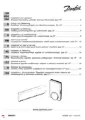
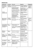
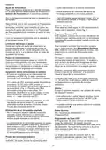
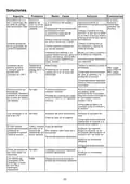
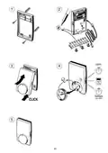

the output marked
☎
.
English
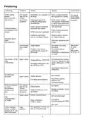
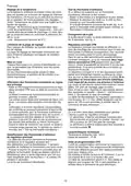
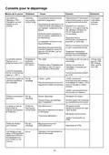
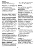
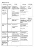
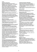
Temperature setting
Set room temperature on the thermostat dial. On
the right-hand side of the thermostat is a function
switch with 3 possible settings:
Test of room thermostat
If a defect in a room thermostat is suspected, the
following test may be carried out:
- Set the thermostat to the highest temperature.
- Move the function switch on the side of the
roomthermostat to a new position.
- If the LED behind the front panel (fig. 4) flashes
quickly for 4 minutes, the room thermostat is
OK.
Sun: The room temperature will be as set on the
thermostat.
Clock: Used only if the zone regulator is engaged.
The temperature will be as set on the room ther-
mostat, but in accordance with the consumption
pattern entered.
The consumption pattern in the zone regulator
can be overridden by moving the switch to sun or
moon.
Battery change
If the battery is getting low, the LED will flash 6 ti-
mes every 6 seconds. See fig. 4.
Master regulator CFM
This regulator governs the individual heat circuits
via wireless communication with the associated
room thermostats. Connection of 8 heat circuits is
enabled.
If more heat circuits are required, connect one or
max. two slave regulators CFS, each with con-
nection for 8 circuits. This allows max. 24 heat cir-
cuits to be governed.
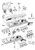
The master/slave is to be fitted immediately
above the distributor pipe on the wall or in a distri-
bution cabinet. Easy access to plugs and termi-
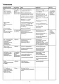
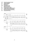
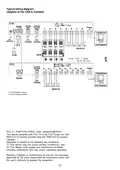
nals should be ensured. See instruction drawing
on the opposite page.
If two slave regulators are connected, move the
jumper in “slave 2” to position 2. See instruction
drawing.
Moon: The room temperature will be as set on the
thermostat - minus 5°C.
Limitation of the setting range
Behind the button for temperature setting are two
lock-pins. These can be placed in the setting knob
as shown in fig. 4 if the thermostat setting range is
to be narrowed.
Putting into operation
Each room thermostat has a unique ID number
preventing conflicts with other thermostats.
A single room thermostat is capable of regulating
several heating outputs, provided these outputs
are assigned to the thermostat.
The connection cable for the slave regulator is 1
m. Cable lengths of up to 100 m are enabled
(available from your electrical items wholesaler)
Assigning thermostats to output(s)
- The installation cable between room thermostat
and CFM (fig. 2) must be connected in assigning
each thermostat to the respective output(s).
- In the LED array the first available output will
flash. The LED in the CFR will also flash.
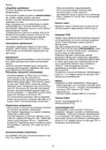
Alarm
There are 2 options with respect to alarms given
by the master regulator:
Outputs already assigned will not be lit (fig. 2).
By pressing OK the thermostat will be assigned
to that output. If the room thermostat is to be as
signed under another lit output, scroll to the output
by means of the +/- keys, then press OK.
- Integral acoustic signal can be selected by
moving the jumper marked “buzzer” from OFF
to ON. See installation drawing.
- External alarm generator can be connected to
- When the installation cable is removed, the red
LED behind the front panel (fig. 4) will flash for
at least 4 minutes. See “Test of room thermostat”
Technical data
Max. ambient temperature 60°C.
Enclosure IP40
Removal of assigned thermostat
- It is not necessary to have the installation
cable in place when removing an assigned
thermostat. Once a thermostat has been
removed, it may be reassigned to another output.
- Removal of room thermostat is done by pressing
OK for 5 seconds, then the entire LED arraywill
be lit. Scroll to the specific room thermostat to
be removed with the +/- button,and press OK
for 5 seconds. The thermostat has now been
removed.
Zone regulator CFZ
The zone regulator governs a maximum of 6 heat
zones. For each heat zone, individual timing
programmes can be connected. For reading and
operating convenience, it is recommended to
place the regulator at eye height.
The connection cable is 5 m. Cable lengths up to
100 m are permitted (available from your electri-
cal items supplier).
2

| General | Details |
|---|---|
| Name | Danfoss CF Wireless Floorheating Controller and Room Thermostat Instruction Manual |
| Make | Danfoss |
| Language | English |
| Filetype | PDF (Download) |
| File size | 0.49 MB |
 (1 votes, average: 5.00 out of 5)
 Loading...

Danfoss RET-MD Electronic Intelligent Dial Setting Thermostat Installation Guide

Danfoss VICUQ24M Icon Programmable II Room Thermostat Installation Guide

Danfoss MBC 8000, MBC 8100 Heavy Duty Thermostat Installation Guide

Danfoss UT 72-UT 73 Universal Thermostat Installation Guide

Danfoss ECtemp 530 Electronic Thermostat Installation Guide

Danfoss 014G0251 Eco Radiator Thermostat User Guide

Danfoss RET230P Electronic Thermostat Instruction Manual

Danfoss 014G0013 Z Wave Radiator Thermostat Installation Guide

Danfoss TP7000 Range Electronic 7 Day Programmable Room Thermostat Installation Guide

Danfoss RET1000 Series Electronic Thermostat User Guide


celect T30 Simple Plug In Thermostat Installation Guide

Tio TEVO Smart RF Wireless Thermostat User Manual

REHAU NEA H 24 V Room Thermostat Instruction Manual

GREYSTONE TLFLF24X01 Flying Lead Low Limit Thermostat Instruction Manual
hager 20441404 Thermostat Owner’s Manual

GENERAL LIFE MITRA-261S Smart Room Thermostat User Manual

SmartLife ZBHTR20WT Zigbee Radiator Thermostat Installation Guide

ENGO Controls EONE230W Internet Controlled Thermostat User Guide

ENGO CONTROLS E10-MBUSW, E10-MBUSB Wi-Fi MODBUS Thermostat User Guide

Fantini Cosmi CH180-230V Touch Screen Programmable Thermostat Instructions