Home > Vive Comfort > VIVE COMFORT TP-S-755 Cool Programmable Thermostat Instruction Manual
VIVE COMFORT TP-S-755 Cool Programmable Thermostat Instruction Manual
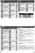

Installation Manual
Installation Tips
Wall Locations
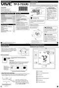
TP-S-755(R)
The thermostat should be installed approximately 4 to 5 feet above the
floor. Select an area with average temperature and good air circulation.
Vive Comfort
P.O. Box 3377
Springfield, MO 65808-3377
Toll Free : 888-776-1427
Do not install
thermostat in locations:
• Close to hot or cold air ducts
• That are in direct sunlight
• With an outside wall behind
the thermostat
• In areas that do not require
conditioning
• Where there are dead spots
or drafts
(in corners or behind doors)
Hours of Operation: M-F 9AM - 6PM Eastern
VM-T755-IM-2431
*VM-755-IM-2431*
Power Type
Thermostat Application Guide
Battery Power
Description
Hardwire (Common Wire)
Hardwire (Common Wire) with
Battery Backup
Gas or Oil Heat
Yes
Yes
Yes
Yes
Electric Furnace
• Where there might be
concealed chimneys or
pipes
Heat Pump (No Aux. or Emergency Heat)
Heat Pump (With Aux. or Emergency Heat)
Multi-Stage Systems
Installation Tip
A trained, experienced
technician must install this
product.
Yes
Yes
Pick an installation location that is easy for
Heat Only Systems
the user to access. The temperature of the
location should be representative of the
building.
Cool Only Systems
Yes
Yes
Carefully read these
instructions. You could damage
this product or cause a
Millivolt
hazardous condition if you fail to
follow these instructions.
Table of Contents
Page
Subbase Installation
Installation Tips
Thermostat Quick Reference
Wiring
Wiring Diagrams
Features
2-3
4-5
6
7-9
10
Horizontal Mount
Vertical Mount
Una version en español de este
manual se puede descargar en
la pagina web de la compañia.
Installation Tip:
Electrical Hazard
Failure to disconnect the power before
beginning to install this product can
cause electrical shock or equipment
damage.
Technician Setup
Programming Thermostat
Specifications
11-19
20-23
24
Mercury Notice
All of our products are mercury free.
However, if the product you are
replacing contains mercury, dispose of
it properly. Your local waste
management authority can give you
instructions on recycling and proper
disposal.
For vertical mount put one screw on the top
and one screw on the bottom.
For horizontal mount put one screw on the
left and one screw on the right.
U.S. Registered Trademark. Patents pending
Copyright 2024 All Rights Reserved.
1
2
Rev. 2431
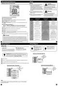
Installation Tips
Thermostat Quick Reference
Mount Thermostat
Getting to know your thermostat
Align the 4 tabs on the subbase with
corresponding slots on the back of the
thermostat, then push gently until the
thermostat snaps in place.
Menu
Battery Installation
Battery installation is optional if thermostat is
hardwired (R and C terminal connected to 24V
power).
Menu
Important:
High quality alkaline batteries are recommended.
Rechargeable batteries or low quality batteries
do not guarantee a 1-year life span.
Insert 2 AA
Alkaline batteries
(included). High
quality alkaline
batteries are
recommended.
LCD Display
Located ont he back of the thermostat.
Glow in the dark light button
About The Private Label Badge
All of our thermostats use the same universal magnetic badge. Visit the
company website to learn more about our free private label program.
Fan Button
System Button
Temperature Setpoint Buttons
User Buttons
Gently slide a screwdriver into the
bottom edge of the badge. Gently turn
the screwdriver counter clockwise. The
Use the bevel on lower ridge
Private Label Badge
badge is held on by a magnet in the well
of the battery door. The badge should pry
off easily. DO NOT USE FORCE.
Magnet in door
4

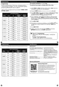
| General | Details |
|---|---|
| Name | VIVE COMFORT TP-S-755 Cool Programmable Thermostat Instruction Manual |
| Make | Vive Comfort |
| Language | English |
| Filetype | PDF (Download) |
| File size | 0.44 MB |


Vive Comfort TP-S-955WH Programmable Thermostat Instruction Manual

VIVE COMFORT TP-N-721 Non Programmable Thermostat Instruction Manual

VIVE COMFORT TP-S-755 Cool Programmable Thermostat Instruction Manual Overview
Summary of Contents
- Page 1: Installation tips include selecting a location approximately 4 to 5 feet above the floor with average temperature and good air circulation. Do not install the thermostat close to hot or cold air ducts, in direct sunlight, with an outside wall behind it, in areas that do not require conditioning, or where there are dead spots or drafts. A trained, experienced technician must install this product. Pick an installation location that is easy for the user to access, ensuring the temperature is representative of the building. Carefully read the instructions to avoid damaging the product or causing hazardous conditions. Electrical hazards can occur if power is not disconnected before installation. All products are mercury-free, but if replacing a mercury-containing product, dispose of it properly. For vertical mount, use one screw on the top and one on the bottom; for horizontal mount, use one screw on the left and one on the right. Battery installation is optional if the thermostat is hardwired, and high-quality alkaline batteries are recommended. The LCD display is located on the back of the thermostat, and the private label badge can be removed using a screwdriver without force.
- Page 2: Thermostat quick reference provides essential information for users. Caution: Electrical hazard warnings are crucial for safety during installation. If replacing a thermostat, note the terminal connections on the existing unit. Failure to disconnect power before installation can cause electrical shock or equipment damage. The low battery indicator alerts users to replace batteries when necessary. The thermostat has four programmable time periods per day. System operation indicators show the current mode of operation. Wiring diagrams and tips are provided for proper installation. Use shielded or non-shielded 18-22 gauge thermostat wire for connections. Installation tips emphasize not overtightening terminal block screws to avoid damage.
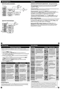
- Page 3: Wiring Diagrams Typical 2H/2C System: 2 Transformer Temporary and Permanent Hold Feature When cool or heat is turned on, the thermostat will display HOLD and RUN SCHED on the left of your screen when you press the or button. Temporary Hold: The temperature will remain at this setpoint temporarily for 4 hours. Permanent Hold: Press the HOLD key to see HOLD appear below the setpoint temperature in the display. To Return to Running Schedule: Press the RUN SCHED button to exit either temporary or permanent hold. Filter Change Reminder: You will see FILT in the display when your air filter needs to be changed. Resetting the filter change reminder: Change your air filter and reset the reminder by holding down the second button from the top left side of the thermostat for 3 seconds. Technician Setup Menu: The swing setting is adjustable from 0.2˚ to 2˚. This thermostat has a technician setup menu for easy installer configuration. The second stage will turn on at 2x the swing setting.
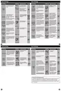
- Page 4: Tech settings allow for various adjustments to heating and cooling stages. The LCD displays adjustment options and defaults for settings. You can select the number of heat and cool stages available. A staging delay feature allows extra time for the previous stage to satisfy the setpoint. Minimum compressor run time can be set to ensure the compressor runs for a specified duration. The system can be configured for different applications such as heat, cool, or auto changeover. Cooling fan delay settings help save energy by controlling fan operation after the compressor shuts off. The thermostat can be programmed for different scheduling options, including 7-day or non-programmable settings. Pro recovery feature allows early heating or cooling to reach setpoints by designated times. Display light settings can be adjusted for intensity and operation based on user preferences.
- Page 5: Tech settings allow for various adjustments and configurations. The LCD will show adjustment options and defaults. You can select ON or OFF for displaying your phone number. The thermostat can energize the Y terminal(s) or W2 terminal based on outdoor temperature. Balance point run time allows the W2 auxiliary terminal to energize even if outdoor temperature is above the selected balance point. You can configure the thermostat for different remote sensor applications. The local and remote temperatures can be averaged. The floor temperature will be displayed when the floor sensor is in use. Programmable thermostats come with an energy-saving pre-program that can be customized. There are four time periods for each program: WAKE, LEAVE, RETURN, and SLEEP.
- Page 6: Set program schedule 5+1+1 or 7 day. To customize your program schedule, follow these steps. All of our programmable thermostats are shipped with an energy saving pre-program. You can customize this default program by following the steps on page 16. Select heat or cool with the system switch. There are four time periods for each program (wake, leave, return, sleep). You can use the table below to plan your customized program schedule. The display range of temperature is 41˚F to 95˚F (5˚C to 35˚C). Your new thermostat has a 5 year limited warranty. You must register your thermostat within 60 days of installation.

Danfoss DEVIreg 530 Electronic Thermostat Installation Guide

SALUS Programmable Wired Thermostat VS30W/VS30B Installation Guide

Danfoss living eco Intelligent Radiator Thermostat User Guide

GENERAL LIFE Therma 300S RF Wireless Room Thermostat User Manual

Honeywell TL7135A Non-Programmable Thermostat User Guide

Digital Touch Thermostat Troubleshooting User Guide

sygonix 2997033 Wi-Fi Radiator Thermostat Instruction Manual

ROMA HEATING RWI5 Wi5 Wi-Fi Digital Heating Thermostat User Manual

EPH CONTROLS RFRA RF Room Thermostat Installation Guide

htc HYT001 WIFI Digital Heating Thermostat User Manual