BlueLink 8205 Smart Wi-Fi Thermostat User Manual


®
User Manual
Universal Smart Wi-Fi Thermostat
This manual covers the following thermostat model:
Up to 3 Heat / 2 Cool Heat Pump
Up to 2 Heat / 2 Cool Conventional
8205
See Wi-Fi Setup Guide for Wi-Fi Setup Instructions
Read all instructions before proceeding.
Store this manual for future reference
8205-110-01

| General | Details |
|---|---|
| Name | BlueLink 8205 Smart Wi-Fi Thermostat User Manual |
| Make | BlueLink |
| Language | English |
| Filetype | PDF (Download) |
| File size | 0.41 MB |


BlueLink 8205 Smart Wi-Fi Thermostat User Manual Overview
Summary of Contents
- Page 1: User manual for the universal smart Wi-Fi thermostat. This manual covers the thermostat model 8205. Up to 3 heat / 2 cool heat pump configurations. Up to 2 heat / 2 cool conventional configurations. See Wi-Fi setup guide for Wi-Fi setup instructions. Read all instructions before proceeding. Store this manual for future reference.
- Page 2: About your thermostat Quick reference Operating your thermostat User settings Accessing user settings Resetting service reminders Setting the time and day Additional operation features Auto changeover mode Thermostat maintenance
- Page 3: Regulatory statements This equipment has been tested and found to comply with the limits for a Class B digital device, pursuant to Part 15 of the FCC Rules. These limits are designed to provide reasonable protection against harmful interference in a residential installation. This equipment generates uses and can radiate radio frequency energy and, if not installed and used in accordance with the instructions, may cause harmful interference to radio communications. If this equipment does cause harmful interference to radio or television reception, the user is encouraged to try to correct the interference by one or more of the following measures. Changes or modifications not expressly approved by the party responsible for compliance could void the user’s authority to operate the equipment. This device complies with part 15 of the FCC Rules. Operation is subject to the following two conditions: (1) This device may not cause harmful interference, and (2) this device must accept any interference received. This device complies with Industry Canada’s licence-exempt RSSs. La operación de este equipo está sujeta a las siguientes dos condiciones: (1) es posible que este equipo o dispositivo no cause interferencia perjudicial y (2) este equipo o dispositivo debe aceptar cualquier interferencia.
- Page 4: About your thermostat
- Page 5: Thermostat functions include various buttons for system control. The SYSTEM button selects the system you want to control. The PROG button enters programming mode or SpeedSet mode. The HOLD button allows entry or exit from program bypass mode. The FAN button selects the system fan mode. The MENU button accesses user settings mode. The Up/Down arrow buttons adjust settings like time and temperature. The Lock/Unlock function is accessed by holding PROG and HOLD together. The battery compartment is located on the back side of the thermostat. Secondary functions of buttons are indicated when in programming or configuration modes.
- Page 6: About your thermostat
- Page 7: Thermostat display includes various indicators and information. Room temperature displays the current room temperature. Set temperature shows the current setpoint temperature. Override indicator indicates that the current program schedule has been temporarily overridden. Time of day displays the current time of day. Message center shows various thermostat status and maintenance information. System mode displays the system mode and current system status. Fan mode indicator indicates the current system fan mode. Fan status indicator shows that the system fan is running. Low battery indicator indicates when the batteries need to be replaced. Wi-Fi indicator indicates the status of the Wi-Fi connection.
- Page 8: User settings allow you to set the current time of day as well as customize various thermostat features. To enter the user settings menu, press and release the menu button. Use the or buttons to select options set. Press next (hold) to confirm this choice and enter the user settings menu. To navigate the user settings menu, press next (hold) or back (prog) to move to the next or previous setting. Use the or buttons to change the selection for each setting. Press return (fan) to exit or wait 30 seconds.
- Page 9: Table of user settings Some user settings may not be available, depending on how the thermostat was configured during installation. Reset filter If a service filter time interval was selected, the thermostat will display a service filter message once that time interval is reached. Select the current hour of day Set the current hour of the day. If the thermostat was configured for a 24-hour clock, the settings 0-24 will be available. Select the current minute of the hour Set the current minute of the hour. Select the current day of the week Set the current day of the week.
- Page 10: Table of user settings Service filter timer is disabled. Select the number of days before receiving a reminder to change your system filter. Temperature hold time lets you select the time that your thermostat will hold the temperature when the HOLD button has been pressed. The thermostat will hold your temperature indefinitely when LONG is selected. The thermostat will hold your temperature for 24 hours when 24HR is selected. Select a 3-digit lock code of 0-9 for each digit. The thermostat lock code sets a 3-digit code that you may use to lock or unlock the thermostat keypad. Setting the 3-digit code does not activate the lock feature. To lock or unlock the thermostat, see Locking/Unlocking Thermostat. The lock code 000 cannot be used.
- Page 11: User settings table includes options for resetting the thermostat. Reset disabled indicates no changes made. Reset enabled allows for thermostat reset. Selecting YES for user reset will reset all user settings, program, and current time. The thermostat lock code and installer settings will not be affected by the reset. The reset will not impact the lock code, wireless connection, or any connected remote sensors. For resetting the wireless connection, refer to the wireless setup guide. An additional table of Wi-Fi settings is available in the Wi-Fi setup guide. This section is part of the user manual.
- Page 12: Setting your program schedule involves several important considerations. Make sure your current time and day of the week are set correctly. Ensure the AM and PM indicators are correct. Various installer settings may affect your programming flexibility. Your NITE event cannot exceed 11:50 p.m. BACK, NEXT, and RETURN are secondary functions of the PROG, HOLD, and FAN buttons. If the thermostat is configured to be non-programmable, you cannot set a program schedule. The thermostat has been configured with one of the following programming options: 7-day programming mode with 4 events per day. 5-2 (weekday/weekend) programming mode with 4 events per day. Non-programmable mode.
- Page 13: Default energy saving programs are pre-programmed in the thermostat. The document outlines pre-programmed times and temperatures for heating and cooling. There are settings for 4 daily events or 2 events in commercial mode. No further programming is necessary if default settings are used. The factory settings include specific times and temperatures for heating and cooling. The heating temperature is set to 70˚ F (21˚ C) during morning and evening events. The cooling temperature is set to 78˚ F (26˚ C) during morning and evening events. Daytime heating is set to 62˚ F (17˚ C) and cooling to 85˚ F (29˚ C). Nighttime heating is also set to 62˚ F (17˚ C) with cooling at 82˚ F (28˚ C). The manual provides details for both 7 day and 5-2 day programming options.
- Page 14: Setting a 7-Day program – All 7 Days at Once (SpeedSet) Setting all 7 days at once will copy over any previously programmed individual days. Available Daily Events: MORN, DAY, EVE, NITE Hold the PROG button for 3 seconds until ALL DAYS appears. Press SYSTEM to select HEAT or COOL. Press or to adjust the hour for the first event. Press or to adjust the minute for the first event. Press or to adjust the temp for the first event. Repeat steps 3-5 for the remaining daily events. Press RETURN to exit.
- Page 15: Setting a 7-Day program – Individual Days Available daily events: MORN, DAY, EVE, NITE Press and release the PROG button. Press SYSTEM to select HEAT or COOL. Press or to select the day you want to program. Press or to adjust the hour for the first event. Press or to adjust the minute for the first event. Press or to adjust the temp for the first event. Repeat steps 4-6 for your remaining daily events. Press RETURN to exit.
- Page 16: Setting a 5-2 day weekday/weekend program is specific to 5-2 day programming mode. Available daily events include morning, day, evening, and night. Press and release the PROG button to start programming. Select HEAT or COOL by pressing the SYSTEM button. Choose between weekdays or weekend and press NEXT. Adjust the hour, minute, and temperature for the first event, pressing NEXT after each adjustment. Repeat the adjustment steps for remaining daily events. You can program additional days by repeating the previous steps if needed. To program the opposite mode, repeat the steps for selection and adjustments. Press RETURN to exit the programming mode.
- Page 17: Operating your thermostat includes setting the system control mode. The system control has five modes of operation: OFF, HEAT, EMR HEAT, AUTO, and COOL. The mode can be selected by pressing the SYSTEM button to scroll through the different system modes. Depending on how your thermostat was configured, some system modes may not be available. OFF means heating and cooling systems are off. HEAT means only your heating system will operate. EMERGENCY operates a backup heat source. HEAT (EMR HEAT) is for heat pump systems only. AUTO allows the system to cycle between heating and cooling automatically based on your temperature set points. COOL means only your cooling system will operate.
- Page 18: Setting the fan control mode has three modes of operation: AUTO, ON, and CIRC. The mode can be selected by pressing the FAN button to scroll through the different fan modes. Depending on how your thermostat was configured, some fan modes may not be available. In AUTO mode, the system fan will run only when your heating or cooling system is running. In ON mode, the system fan stays on continuously. In CIRC mode, the system fan will run periodically to help circulate air and provide more even temperature when the heating or cooling system is not active.
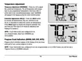
- Page 19: Temperature adjustment options include temporary adjustment (override) and extended adjustment (hold). Temporary adjustment allows you to change the current set temperature, which will revert to the programmed temperature later. The override feature will display OVERRIDE during the adjustment period. Extended adjustment lets you override all programming by pressing the hold button. You can continue to adjust the temperature while in hold mode. Pressing the hold button again will resume the program schedule. Hold time can be limited to 24 hours by adjusting User Setting 6. If the thermostat is non-programmable, hold and override features are not available. Program event indicators show which part of the current program is active. In non-programmable or hold mode, program event and override indicators will not be displayed.
- Page 20: System status and maintenance indicators provide messages or symbols in the display to inform you of the system's current function. The heating system is running. The cooling system is running. The auxiliary stage of heating is running (multistage systems only). The emergency heating system is running (heat pump systems only). Indicates that the system fan is running.
- Page 21: System status and maintenance indicators provide important information about the device's performance. High limit indicates that the setpoint temperature has reached its upper limit maximum. Low limit indicates that the setpoint temperature has reached its lower limit maximum. Hi temp shows that the room temperature has risen above the display range, but cooling will still operate. Lo temp indicates that the room temperature has fallen below the display range, but heating will still operate. The battery symbol appears when batteries are installed and become low. When batteries are critically low, the battery symbol will flash, and a change/battery message will alternate in the display. Refer to section 6 for instructions on changing the batteries.
- Page 22: System status and maintenance indicators provide important information about the thermostat's operation. The thermostat can be fully or partially locked. Refer to the section on locking and unlocking the thermostat for more details. A user-selectable service reminder for changing the filter has been triggered. Instructions for setting or resetting these reminders can be found in the user options section. Loss of AC power to the thermostat indicates a power issue. This status is only available if the thermostat is hardwired and configured for power monitoring. A flashing Wi-Fi icon signifies an interrupted Wi-Fi network connection. Typically, the connection will re-establish when the network is available. For persistent issues, consult the Wi-Fi setup guide for further instructions.
- Page 23: Auto changeover mode allows the system to switch between heating and cooling based on room temperature. The thermostat maintains a forced separation between heating and cooling setpoints to prevent conflicting operations. If a setting violates the forced separation, the opposite mode adjusts accordingly. Select auto changeover mode by pressing the SYSTEM button until AUTO HEAT or AUTO COOL appears. Adaptive recovery mode attempts to reach the desired temperature at the scheduled time after a setback period. For example, if the heat is set to 62° at night and 70° is scheduled for 7:00 AM, the heating system may turn on early. This feature does not operate in HOLD mode or when the program is overridden. Emergency heat selection on a multistage heat pump system disables this feature.
- Page 24: Circulating Fan Mode is selected by touching the FAN button until CIRC appears in the display. When in CIRC mode, the fan operates as required by the heating and cooling system. When heating or cooling is not active, the fan will run as needed to ensure a 35% minimum run time. This thermostat includes an automatic compressor protection delay to avoid potential damage to your system from short cycling. This feature activates a short delay after turning off the system compressor. For multistage heat pump systems, this thermostat provides cold weather compressor protection by locking out the compressor stage(s) of heating after a power outage greater than 60 minutes. During this lockout period, the thermostat will operate the auxiliary stage of heating.
- Page 25: Locking and unlocking the thermostat. Your 3-digit lock code is set in the User Settings portion of this manual. To lock or unlock the thermostat, press and hold the PROG and HOLD buttons together for 5 seconds. LOCK will flash in the display. The screen will change displaying LOCK CODE 000. Press or to enter the first digit of your lock code and then press the NEXT button to advance to the next digit. After entering the third digit, press NEXT to advance to the next User Setting or RETURN to exit. If you entered a valid code, the thermostat will be locked or unlocked. When locked, the word LOCKED appears in the display. If an invalid code is entered, WRONG CODE will briefly appear in the display.
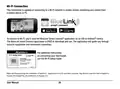
- Page 26: Wi-Fi connection allows remote monitoring and control from a mobile device or PC. To connect to Wi-Fi, download the BlueLink Smart Connect application on an iOS or Android device. The BlueLink Smart Connect application is free to download and use. The application will guide you through account registration and thermostat connection. Refer to the Wi-Fi Setup Guide for additional instructions on connecting your thermostat. Apple and the Apple logo are trademarks of Apple Inc. App Store is a service mark of Apple Inc. Google and Google Play are trademarks of Google LLC.
- Page 27: Thermostat maintenance includes changing the batteries and cleaning the device. The thermostat may require two AA type alkaline batteries. A low battery symbol will appear when the batteries are low. When batteries are critically low, the battery symbol will flash, and a change/battery message will alternate in the display. To change the batteries, remove the thermostat body, replace old batteries, and ensure correct positioning of the (+) and (-) symbols. It is recommended to replace the thermostat batteries annually or if the thermostat will be unattended for an extended period. For cleaning, never spray liquid directly on the thermostat. Use a soft cloth with cleaning liquid to clean the screen. Only water or household glass cleaner should be used, avoiding abrasive cleansers.
- Page 28: Limited warranty When installed by a professional contractor, this product is backed by a 5 year limited warranty. Limitations apply. For limitations, terms and conditions, you may obtain a full copy of this warranty.

hansgrohe 15763003 Shower Select Thermostat Instruction Manual

WHITE-RODGERS 1F86-444 Non Programmable Electronic Digital Thermostat Instruction Manual

ARISTON 3319126 CUBE S NET Wi-Fi Thermostat User Manual

BEOK CONTROLS TGR86 WiFi Thermostat User Guide

GENERAL FH101S Underfloor Heating Thermostat User Manual

Honeywell Y460A2003 Creative Series Thermostat Installation Guide

tado 104388 Smart Thermostat

ideal HEATING Halo Combi RF Wireless Boiler Thermostat User Guide

LUX PSP511A Series Programmable 5-2 Thermostat Instruction Manual

nVent RAYCHEM AT-TS-13 Surface Sensing Thermostat Instruction Manual