Home > Xetron > Xetron STC-1000Pro Smart Digital Thermostat User Manual

Xetron STC-1000Pro Smart Digital Thermostat User Manual
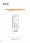
Smart Temperature Controller Series  
STC-1000Pro User Manual  
Smart Digital Thermostat  
No wiring , No hassle  
GeneralDetails
NameXetron STC-1000Pro Smart Digital Thermostat User Manual
MakeXetron
LanguageEnglish
FiletypePDF (Download)
File size2.37 MB
Download PDF
1 Star2 Stars3 Stars4 Stars5 Stars (1 votes, average: 5.00 out of 5)
Loading...

Xetron STC-1000Pro Smart Digital Thermostat User Manual
Get the free PDF manual for the Xetron STC-1000Pro Smart Digital Thermostat User Manual and access setup steps, usage instructions, and troubleshooting tips. 👉 View online or download now to keep your thermostat running smoothly!
Xetron STC-1000Pro Smart Digital Thermostat User Manual Overview
Summary of Contents

  • Page 1: Smart temperature controller series STC-1000Pro user manual Smart digital thermostat No wiring, no hassle
  • Page 2: Smart temperature controller series STC-1000Pro user manual Intelligente temperaturregler-serie STC-1000Pro benutzerhandbuch Serie del controlador de temperatura inteligente Manual de uso de STC-1000Pro Série de thermostat intelligent Mode d’emploi STC-1000Pro Serie di termostati intelligenti Manuale di istruzione di modello STC-1000Pro
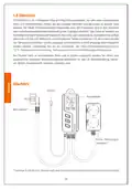
  • Page 3: Overview The STC-1000Pro is a plug-and-play smart digital temperature controller. It has two pre-wired heating and cooling outlets that automatically keep your appliances at ideal temperatures. The device is made from V-O classified flame-retardant ABS materials for safety and reliability. Its three-button design and 2.5 LCD provide intuitive temperature viewing and parameter settings. Features include high/low temperature alarm, temperature calibration, C/F unit switch, and cooling protection time. The STC-1000Pro can be widely used in areas that require automatic temperature controls, such as homebrewing and aquariums. Included in the box are a temperature probe, main controller, power plug, and cooling and heating outlets. Available versions include UK, EU, and US.
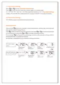
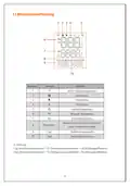
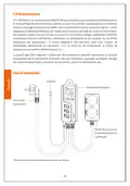
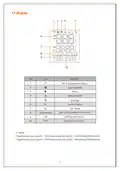
  • Page 4: Display section includes various icons and their functions. Wi-Fi connection status is indicated on the display. Cooling mode and heating mode are represented by specific icons. An alarm icon is present to indicate alerts. Settings can be accessed through the display. Current value and set value are shown for monitoring. Cooling start point (Csp) and heating start point (Hsp) are defined. Csp is calculated as the temperature set-point plus the cooling differential. Hsp is calculated as the temperature set-point minus the heating differential. Refer to section 3.0 for parameter instructions.
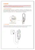
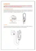
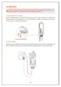
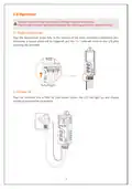
  • Page 5: Operation may cause serious damage to you or your device. Please make sure you read and understand the following procedures before starting. Plug the temperature probe fully to the bottom of the main controller's headphone jack. A buzzer alarm will be triggered, and the Err code will show on the LCD after powering the controller. Plug the controller into a 100V to 250V power outlet, the LCD will light up and display temperature and other parameters.
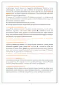
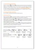
  • Page 6: Parameter viewing mode allows users to view parameters and relative values in ascending order: TS, CD, HD, PT, AH, AL, CA. The controller will automatically exit viewing mode after 5 seconds of inactivity. STC-1000Pro supports parameter settings by buttons. Press and hold the button to enter the parameter setting mode, indicated by a beep and the LCD display. Users can switch to the next parameter and adjust the setting value using designated buttons. Press and hold for 3 seconds to save settings and exit. The controller will save and exit setting mode after 15 seconds of inactivity. A flow chart is provided for quick parameter setting procedures. Parameters include heating and cooling differential, temperature set value, protection time, and alarm limits. Temperature calibration is also a part of the parameter settings.
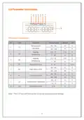
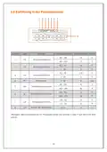
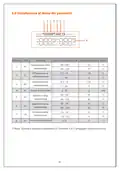
  • Page 7: Parameter instructions provide essential settings for temperature control. The code TS indicates the temperature set-point range from -40 to 110°C and -40 to 230°F. The default temperature set-point is 25°C or 77°F. Differential settings range from 0.2 to 15 for both cooling and heating. Protection time is adjustable from 0 to 10 minutes. High alarm limit can be set between -40 to 110°C and -40 to 230°F. Low alarm limit is set at 32°F or 0°C. Temperature calibration is available with a default of 0. The temperature unit can be switched between Celsius and Fahrenheit. The °C/°F icon will flash on the LCD during temperature unit settings.
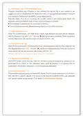
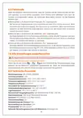
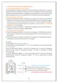
  • Page 8: Parameter functions include temperature setting, heating differential, and cooling differential. The controller displays the current value (PV) and the set value (SV) based on the temperature set-point (TS), heating differential (HD), and cooling differential (CD). In cooling mode, if the current value (PV) is greater than or equal to the cooling start point (Csp), the controller activates cooling. If the cooling icon flashes, the compressor is in protection status. In heating mode, if the current value (PV) is less than or equal to the heating start point (Hsp), the controller activates heating. The controller exits cooling mode when the current value (PV) is less than or equal to the temperature set-point (TS). The controller exits heating mode when the current value (PV) is greater than or equal to the temperature set-point (TS). Example settings include a temperature set-point (TS) of 25°C, cooling differential (CD) of 3°C, and heating differential (HD) of 3°C. The cooling start point (Csp) is calculated as TS + CD, while the heating start point (Hsp) is calculated as TS - HD. The controller automatically switches between cooling and heating modes based on the current value (PV) in relation to the set points.
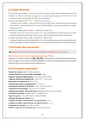
  • Page 9: Protection time (PT) helps prevent frequent start/stop issues that may shorten appliance service life. Setting PT according to requirements is recommended. When PT is set to 3 minutes, the controller enters cooling mode if certain conditions are met. High alarm limit (AH) triggers a high temperature alarm when the current value exceeds this limit. The LCD displays error code EAH during a high temperature alarm. Low alarm limit (AL) triggers a low temperature alarm when the current value falls below this limit. The LCD displays error code EAL during a low temperature alarm. The controller operates normally during AH or AL alarms. Temperature calibration (CA) allows correction of the current value if it deviates from the standard. The controller supports both Celsius and Fahrenheit displays, with defaults based on region.
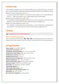
  • Page 10: Installation For your personal and appliance's safety, we suggest you power on the controller after the installation finishes. This controller supports hanging-mount only; please check and confirm the installation distances and nails size before installation. Cooling/Heating Outlet Take care when using electricity. Please plug your refrigeration and heating appliances into the corresponding cooling and heating outlets to the controller. If all status is normal, the controller will start cooling or heating automatically according to the parameters. Note: If you only need to connect one appliance, or do not use the outlet for a long time, please put it away to prevent potential damage to the controller.
  • Page 11: Error code alerts the user through a buzzer and LCD display. Err indicates a probe issue; re-install or replace the probe if the code persists. EAH signifies a high temperature alarm; check immediately to prevent damage. EAL indicates a low temperature alarm; check immediately to prevent damage. To reset the controller, power it on and hold all three buttons until the screen turns off. The controller will auto-restart after resetting to default parameters. Power supply ranges from 100 to 250VAC at 50/60Hz. Temperature measuring range is from -45°C to 115°C. Operating ambient temperature is between -10°C and 65°C. Dimensions of the controller are 165 x 60 x 32 mm.
  • Page 12: STC-1000Pro ist ein intelligenter Plug-and-Play-Temperaturregler mit zwei vorverdrahteten Kühl- und Heizsteckdosen. Die Steckdosen sind in drei Versionen nach britischem, europäischem und amerikanischem Standard erhältlich. Das Gehäuse besteht aus flammhemmendem Material der Klasse V0. Das Bedienfeld verfügt über einen 2,5-Zoll-LCD-Bildschirm und einfache Drei-Tasten-Funktionen. Es bietet Funktionen wie Hoch-/Niedrigtemperaturalarm und °C/°F-Temperaturumwandlung. Das Produkt kann in verschiedenen Anwendungen eingesetzt werden, die eine automatische konstante Temperaturregelung erfordern. Anwendungsbeispiele sind Weinherstellung, Aquarium, Brüten, Haustierzucht, Gärtnerei und Gärkultur. Das Gerät ermöglicht eine intuitive Anzeige von Temperaturstatistiken und eine schnelle Einstellung von Parametern. Kühlleistungsschutzzeit ist eine der zusätzlichen Funktionen des Geräts. Das Produkt ist sicher und zuverlässig in der Anwendung.
  • Page 13: Bildschirmeinführung Wi-Fi-Verbindungsstatus Kühlmodus Warnstatus Heizmodus Einstellungsmodus Aktuelle Temperatur Einstelltemperatur Kühlstarttemperatur Heizstarttemperatur Achtung: Csp (Kühlstarttemperatur) = TS (Temperatureinstellwert) + CD (Kühlungsdifferenz) Hsp (Heizstarttemperatur) = TS (Temperatureinstellwert) - HD (Heizungsdifferenz)
  • Page 14: Betrieb Wichtig: Unsachgemäße Verwendung kann zu Personen- und Produktschäden führen. Bitte lesen, verstehen und befolgen Sie die folgenden Schritte. Sensorinstallation Stecken Sie den Temperatursensor zur Installation vollständig in das Kopfhörerloch unter dem Temperaturregler. Andernfalls werden nach dem Einschalten ein akustischer und optischer Alarm ausgelöst und ein „Err“-Fehlercode auf dem LCD angezeigt. Einschalten Stecken Sie den Netzstecker des Reglers in die Steckdose von 100 V bis 250 VAC, wenn der LCD-Bildschirm aufleuchtet und die Temperatur und andere Parameter anzeigt.
  • Page 15: Parameteranzeige Klicken Sie auf die Taste, um den Parameteranzeigemodus aufzurufen. Drücken Sie die Taste, um die Parameter und ihre Werte in aufsteigender Reihenfolge anzuzeigen: TS → CD → HD → PT → AH → AL → CA. Eine ausführliche Beschreibung der Parameter finden Sie im nächsten Schritt „2.4 Parametereinstellungen“. Hinweis: Im Ansichtsmodus wird der Ansichtsstatus automatisch beendet, wenn nach 5 Sekunden keine Bedienung erfolgt. Parametereinstellungen Der STC-1000Pro unterstützt das Einstellen von Parametern über Tasten. Halten Sie die Taste, um in den Parametereinstellungsmodus zu gelangen. Drücken Sie die Taste, um zur nächsten Parameter zu wechseln, und drücken Sie dann die Taste 3 Sekunden lang, um in den Parametereinstellungsmodus zu gelangen. Halten Sie die Taste 3 Sekunden lang gedrückt, um die Einstellungen zu speichern. Nach 15 Sekunden ohne Bedienung speichert das System die Parameter automatisch und verlässt den Parametereinstellungsmodus. Im folgenden Flussdiagramm finden Sie Informationen zur schnellen Parametereinstellung.
  • Page 16: Einführung in das Parametermenü Einstellungsbereich Standardwerte Einstelltemperatur Kühlungsdifferenz Heizungsdifferenz Schutzzeit Hochtemperaturalarm Niedrigtemperaturalarm Temperaturkorrektur Einheit der Temperatur
  • Page 17: Einführung der Parameterfunktion Einstelltemperatur - TS, HD, CD & PV, SV Wenn der Regler ordnungsgemäß funktioniert, zeigt PV die aktuell gemessene Temperatur an und SV ist der Temperatureinstellwert. Sie können den Arbeitszustand von Kühlen oder Heizen automatisch umschalten, indem Sie die Parameter TS, HD und CD einstellen. Kühlmodus aktivieren: Wenn PV größer oder gleich TS + CD ist, wechselt der Regler in den Kühlmodus. Wenn PV kleiner oder gleich TS ist, wird der Kühlmodus des Systems beendet. Heizmodus aktivieren: Wenn PV kleiner oder gleich TS - HD ist, wechselt das System in den Heizmodus. Wenn PV größer oder gleich TS ist, verlässt das System den Heizmodus. Beispiel: Einstellung TS = 25 °C, CD = 3 °C, HD = 3 °C. Wenn die PV größer oder gleich 28 °C ist, wechselt der Regler automatisch in den Kühlmodus. Wenn die PV kleiner oder gleich 25 °C ist, verlässt der Regler automatisch den Kühlmodus. Wenn die PV kleiner oder gleich 22 °C ist, wechselt der Regler automatisch in den Heizmodus.
  • Page 18: Schutzzeit - PT gilt nur für den Kühlmodus. Häufiges Starten und Ausschalten kann die Lebensdauer des Geräts beeinflussen. Der Temperaturregler wartet auf eine Kühlstartverzögerungszeit, um das Gerät zu schützen. Es wird empfohlen, die Schutzzeit entsprechend den tatsächlichen Bedürfnissen einzustellen. Hochtemperaturalarm-AH wird ausgelöst, wenn die Messtemperatur den Hochtemperaturalarm erreicht. Ein Fehlercode „EAH“ wird angezeigt, und der Summer gibt einen Piepton aus. Der Fehlercode bleibt bestehen, bis die Messtemperatur unter den Hochtemperaturalarm fällt. Niedrigtemperaturalarm-AL wird ausgelöst, wenn die Messtemperatur den Niedrigtemperaturalarm erreicht. Ein Fehlercode „EAL“ wird angezeigt, und der Summer gibt einen Piepton aus. Der Fehlercode bleibt bestehen, bis die Messtemperatur über den Niedrigtemperaturalarm steigt. Temperaturkorrektur – CA ermöglicht die Korrektur der Messtemperatur, wenn sie von der Standard- oder Isttemperatur abweicht. Der Kalibrierungswert kann positiv, 0 oder negativ sein. Fahrenheit oder Celsius-CF unterstützt die Anzeige in Celsius oder Fahrenheit. Der Regler verwendet standardmäßig Fahrenheit oder Celsius, abhängig vom Standard. Der Parameter CF kann geändert werden, um die bevorzugte Einheit einzustellen.
  • Page 19: Geräteinstallation Zu Ihrer persönlichen Sicherheit und zur Sicherheit Ihres Geräts empfehlen wir, den Regler nach Abschluss der Installation einzuschalten. Dieses Gerät unterstützt nur Aufhängeinstallation. Bitte überprüfen Sie vor der Installation die Installationsabstände und die Schraubengröße gemäß dem Verwendungsszenario. Spezifische Installationsskizzen und Abmessungen werden wie folgt empfohlen: Φ 9mm, Φ 7mm. Kühl-/Heizsteckdose Vorsicht beim Umgang mit Strom! Bitte stecken Sie Ihr Gerät mit Kühl-/Heizfunktion in die entsprechende Kühl- und Heizsteckdose des Reglers. Befindet sich das Gerät in einem normalen Zustand, schaltet der Regler die Kühl- oder Heizfunktion gemäß den eingestellten Temperaturparametern automatisch ein. Wenn Sie nur ein externes Gerät anschließen müssen oder die Steckdose längere Zeit nicht benutzen, achten Sie bitte darauf, die Steckdose zu schützen.
  • Page 20: Fehlercode Wenn die folgenden Umstände auftreten, piept der Summer und der Fehlercode wird auf dem LCD angezeigt. Wenn auf dem LCD-Bildschirm der Fehlercode „Err“ angezeigt wird: Der Sensor ist möglicherweise nicht angeschlossen oder nicht richtig installiert. Wenn auf dem LCD-Bildschirm der Fehlercode „EAH“ angezeigt wird: Der Regler befindet sich im Hochtemperaturalarmstatus. Wenn auf dem LCD-Bildschirm der Fehlercode „EAL“ angezeigt wird: Der Regler befindet sich im Niedrigtemperaturalarmstatus. Alle Einstellungen wiederherstellen Der Regler kann durch Einschalten der Stromversorgung wiederhergestellt werden. Standardparameterwert wiederherstellen: Halten Sie alle drei Tasten auf dem Bedienfeld des Temperaturreglers lange gedrückt. Technische Parameter Betriebsspannung: 100~250VAC, 50/60Hz. Temperaturmessbereich: -45°C ~115°C/-49°F~239°F.
  • Page 21: Introducción STC-1000Pro es el controlador de temperatura inteligente que utiliza dos tomacorrientes de refrigeración y calentamiento preconectados. Su cáscara es de material ignífugo del nivel V0, que es seguro y confiable. Su panel utiliza una pantalla LCD de 2,5 pulgadas con tres botones simples. Ofrece funciones como la alarma de alta y baja temperatura, conmutación de °C/°F, calibración de temperatura y tiempo de protección de salida de refrigeración. El producto se puede aplicar en sitios y aparatos que necesitan control de temperatura constante automático, como la fermentación y destilación de bebidas alcohólicas, acuario, incubación, cría de animales, siembra y cultivo de plantas.
  • Page 22: Introducción de pantalla Estado de conexión de Wi-Fi Modo de refrigeración Estado de alarma Modo de calentamiento Modo de configuración Temperatura actual Temperatura configurada Atención: Csp (temperatura inicial de refrigeración) = TS (temperatura configurada) + CD (diferencia de retorno de refrigeración) Atención: Hsp (temperatura inicial de calentamiento) = TS (temperatura configurada) – HD (diferencia de retorno de calentamiento)
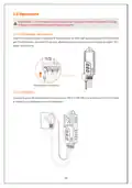
  • Page 23: Operación Atención: El uso incorrecto puede provocar lesiones corporales y deterioros del producto. Lea, comprenda y ejecute los siguientes pasos. Instalación del sonda Inserte el sonda de temperatura en los auriculares en la parte inferior del controlador de temperatura completamente para realizar la instalación. Inicio Inserte el enchufe de alimentación del controlador en el tomacorriente de 100V a 250VCA, la pantalla LCD se encenderá y visualizará la temperatura y otros parámetros.
  • Page 24: Consultar parámetros permite acceder a los valores de configuración. El modo de consulta se activa al presionar un botón específico. Los parámetros se visualizan en una secuencia definida. El sistema saldrá del estado de consulta automáticamente tras 5 segundos de inactividad. La configuración de parámetros se realiza mediante un botón. Se debe mantener presionado un botón durante 3 segundos para entrar en el modo de configuración. El zumbador sonará al ingresar al modo de configuración. Los valores configurados se pueden aumentar o reducir usando botones específicos. Las configuraciones se guardan al mantener presionado un botón durante 3 segundos. El sistema también guarda automáticamente los parámetros tras 15 segundos de inactividad.
  • Page 25: Introducción del menú de parámetros Función Alcance de configuración Valor por defecto Unidad Temperatura configurada Diferencia de retorno de refrigeración Diferencia de retorno de calentamiento Tiempo de protección Alarma de alta temperatura Calibración de temperatura
  • Page 26: Introducción de funciones de parámetros Temperatura configurada Cuando el controlador funciona normalmente, PV indica la temperatura medida actual, y SV indica el valor de temperatura configurado. Entrada en el modo de refrigeración: Cuando PV (temperatura medida) ≥ TS (temperatura configurada) + CD (diferencia de retorno de refrigeración), el controlador entra en el modo de refrigeración. Cuando PV (temperatura medida) ≤ TS (temperatura configurada), el sistema sale del modo de refrigeración. Entrada en el modo de calentamiento: Cuando PV (temperatura medida) ≤ TS (temperatura configurada) – HD (diferencia de retorno de calentamiento), el sistema entra en el modo de calentamiento. Cuando PV (temperatura medida) ≥ TS (temperatura configurada), el sistema sale del modo de calentamiento. Ejemplo: Cuando configuran TS = 25°C, CD = 3°C, HD = 3°C, Csp (temperatura inicial de refrigeración) = TS + CD = 28°C; Hsp (temperatura inicial de calentamiento) = TS - HD = 22°C.
  • Page 27: Tiempo de protección – PT (sólo aplicable al modo de refrigeración) El controlador de temperatura no inicia a refrigerar inmediatamente después de configurar estos parámetros, sino espera un tiempo de retardo llamado PT. Se recomienda que lo configure de acuerdo con las necesidades reales. El controlador entrará en el modo de refrigeración después de cumplir con ciertas condiciones. Alarma de alta temperatura — AH Cuando la temperatura medida es mayor o igual a la alarma de alta temperatura, se activa la alarma. La pantalla visualiza el código de alarma “EAH” y el icono correspondiente. El controlador funciona normalmente durante la alarma. Alarma de baja temperatura — AL Cuando la temperatura medida es menor o igual a la alarma de baja temperatura, se activa la alarma. La pantalla visualiza el código de alarma “EAL” y el icono correspondiente. El controlador funciona normalmente durante la alarma. Calibración de temperatura — CA Se podrá realizar la calibración si existe desviación entre la temperatura medida y la temperatura estándar. El valor calibrado puede ser positivo, 0 o negativo. Grado Fahrenheit o Centígrado — CF El controlador soporta la visualización en centígrado o grado Fahrenheit. Si es diferente a su preferencia, modifique los parámetros de CF.
  • Page 28: Dispositivos de instalación deben ser utilizados después de la instalación para seguridad. El aparato solo soporta la instalación en suspensión. Es importante inspeccionar la distancia de instalación y la dimensión del tornillo según el escenario de uso. Se proporciona un diagrama esquemático de instalación y dimensiones específicas. Se debe tener cuidado con la seguridad eléctrica al usar el tomacorriente de refrigeración y calentamiento. Los aparatos deben ser insertados en el tomacorriente correspondiente para activar funciones automáticamente. El controlador puede activar la función de refrigeración o calentamiento según los parámetros de temperatura configurados. Los iconos de estado de trabajo se encenderán para indicar el estado actual del aparato. Si solo se necesita conectar un aparato exterior, es importante proteger el tomacorriente. Se debe evitar el deterioro del aparato o riesgos de seguridad al no utilizar el tomacorriente por largo tiempo.
  • Page 29: Código de alarma y funcionamiento del zumbador. El zumbador dará la alarma acústica y el código de alarma aparecerá en la pantalla. El código de falla Err indica que el sonda no se conecta o no se inserta correctamente. El código de falla EAH indica la alarma de alta temperatura, donde la temperatura actual supera el valor de alarma. El código de falla EAL indica la alarma de baja temperatura, donde la temperatura actual es inferior al valor de alarma. Para realizar la restauración, conecte el controlador a la alimentación. Mantenga presionados todos los botones en el panel del controlador hasta que la pantalla se apague. Tensión de trabajo: 100~250VAC, 50/60Hz. Alcance de medición de temperatura: -45 °C ~115°C. Dimensión del producto: 165 x 60 x 32 mm.
  • Page 30: Présentation STC-1000Pro est un thermostat intelligent PnP qui utilise deux prises femelles de refroidissement et de chauffage pré-connectées pour faciliter la sortie et contrôler l’appareil pour qu’il maintienne toujours une plage de température idéale. Ses prises femelles ont trois versions en option : norme anglaise/européenne/américaine. Son boîtier est en matériau ignifuge de classe V0 sûr et fiable. Son panneau utilise un écran LCD de 2,5 pouces et trois boutons simples, permettant d’afficher visuellement diverses informations statistiques de température. Il fournit également des fonctions telles que l’alarme de haute/basse température, la conversion °C/°F, la correction de température, le temps de protection de la sortie de refroidissement, etc. Le produit peut être largement utilisé dans divers locaux et appareils nécessitant un contrôle automatique de la température constante, tels que vinification, aquarium, incubation, élevage des animaux domestiques, culture des jeunes plants, culture de fermentation, etc.
  • Page 31: Présentation de l’écran État de connexion Wi-Fi Mode de refroidissement État d’alarme Mode de chauffage Mode de configuration Température actuelle Température définie Csp (température de départ de refroidissement) = TS (température définie) + CD (différence de retour de refroidissement) Hsp (température de départ de chauffage) = TS (température définie) - HD (différence de retour de chauffage)
  • Page 32: Opération Une utilisation incorrecte peut entraîner des dommages au personnel et au produit. Veuillez lire, comprendre et suivre les étapes ci-dessous. Installation de capteur Insérez complètement le capteur de température dans le jack d’écouteur au-dessous de thermostat pour l’installation, sinon, il y aura une alarme sonore et lumineuse et une indication de code « Err » après le démarrage. Démarrage Branchez la prise mâle d’alimentation du thermostat dans la prise femelle d’alimentation de 100V à 250VAC, et l’écran LCD s’allume et affiche la température et d’autres paramètres.
  • Page 33: Consultation des paramètres Appuyez sur le bouton pour passer en mode de consultation des paramètres. Consultez les paramètres et leurs valeurs dans l’ordre positif. Pour une présentation détaillée de chaque paramètre, veuillez-vous rapporter à l’étape suivante « 2.4 Configuration des paramètres ». En mode de consultation, si aucune opération n’est effectuée après 5 secondes, l’état de consultation se ferme automatiquement. Configuration des paramètres Pour STC-1000Pro, configurez les paramètres à l’aide des boutons. Appuyez sur le bouton et maintenez-le pendant 3 secondes pour passer en mode de configuration des paramètres. Appuyez à nouveau sur le bouton pour commuter les paramètres. Appuyez sur le bouton pour augmenter ou diminuer la valeur définie. Une fois la définition terminée, appuyez sur le bouton et maintenez-le pendant 3 secondes pour la sauvegarde. Le système sauvegarde automatiquement les paramètres après 15 secondes sans opération. Le diagramme de configuration des paramètres vous aide à comprendre rapidement tout le processus de configuration.
  • Page 34: Présentation du menu de paramètres Plage de configuration Valeur par défaut Code Fonction Unité Température définie Différence de retour de refroidissement Alarme de haute température Alarme de basse température Correction de température
  • Page 35: Présentation des fonctions de paramètre Définition de température - TS, HD, CD & PV, SV Lorsque le thermostat fonctionne normalement, PV affiche la température mesurée actuelle, SV est la valeur définie de température. Vous pouvez définir les paramètres TS, HD et CD pour réaliser l’état de fonctionnement de commutation automatique de refroidissement ou de chauffage. Mode de refroidissement : Lorsque PV ≥ TS + CD, le thermostat passe en mode de refroidissement. Si le symbole de refroidissement clignote, il signifie qu’il se trouve dans l’état de protection de compresseur. Mode de chauffage : Lorsque PV ≤ TS - HD, le système passe en mode de chauffage. Lorsque PV ≥ TS, le système quitte le mode de chauffage. Exemple : Lorsque TS = 25°C, CD = 3°C, HD = 3°C, Csp = TS + CD = 28°C ; Hsp = TS - HD = 22°C. Lorsque PV ≥ 28°C, le thermostat passe automatiquement en mode de refroidissement. Lorsque PV ≤ 22°C, le thermostat passe automatiquement en mode de chauffage.
  • Page 36: Temps de protection - PT (uniquement pour mode de refroidissement) Les démarrages et arrêts fréquents de l’appareil de refroidissement affectent ou même endommagent sa durée de vie. Le thermostat ne commence pas à refroidir immédiatement mais attend un délai de retard, soit PT (temps de protection). Il est recommandé d’effectuer la définition en fonction de besoins réels. Alarme de haute température - AH Lorsque PV (température mesurée) ≥ AH (alarme de haute température), l’alarme de haute température se produit. Le code d’alarme « EAH » et l’icône s’affichent sur l’écran, et le buzzer émet une alarme sonore. Cette fonction d’alarme n’est utilisée comme indication, et le thermostat fonctionne normalement pendant l’alarme. Alarme de basse température - AL Lorsque PV (température mesurée) ≤ AL (alarme de basse température), l’alarme de basse température se produit. Le code d’alarme « EAL » et l’icône s’affichent sur l’écran, et le buzzer émet une alarme sonore. Cette fonction d’alarme n’est utilisée comme indication, et le thermostat fonctionne normalement pendant l’alarme. Correction de température - CA Si la température mesurée diffère de la température standard ou réelle, elle peut être corrigée par le paramètre CA. La valeur de correction peut être positive, 0 ou négative. Degrés Fahrenheit ou Celsius - CF Le thermostat affiche en degrés Celsius ou Fahrenheit, degrés Fahrenheit par défaut pour le thermostat en norme américaine. S’il diffère de votre préférence, veuillez modifier les paramètres CF.
  • Page 37: Installation de l'appareil doit être effectuée avec précaution pour garantir la sécurité. L'appareil ne peut être installé qu'en suspension, et il est important de vérifier la distance d'installation et la taille des vis. Le schéma d'installation spécifique et la taille recommandée sont Φ 9mm et Φ 7mm. Il est crucial de faire attention à la sécurité de l'électricité lors de l'utilisation de la prise femelle de refroidissement/chauffage. Les appareils avec fonction de refroidissement/chauffage doivent être insérés dans la prise femelle correspondante du thermostat. Le thermostat active automatiquement la fonction de refroidissement ou de chauffage selon les paramètres de température définis. Les symboles sur le panneau s'allument pour indiquer l'état de fonctionnement actuel. Si un seul appareil est nécessaire ou si la prise femelle n'est pas utilisée pendant une longue période, il est conseillé de la protéger contre les dommages.
  • Page 38: Codes de panne Le buzzer émet une alarme sonore et le code d’alarme sur l’écran s’allumera. Lorsque le code de panne « Err » s’affiche sur l’écran LCD, cela indique que le capteur n’est pas connecté ou inséré correctement. Lorsque le code de panne « EAH » s’affiche sur l’écran LCD, cela indique l’alarme de haute température. Lorsque le code de panne « EAL » s’affiche sur l’écran LCD, cela indique l’alarme de basse température. Fonction de restauration Mettez le thermostat sous tension pour effectuer l’opération de restauration. Appuyez sur tous les boutons + sur le panneau du thermostat pour restaurer les valeurs de paramètres par défaut. Paramètres techniques Tension de service : 100~250VAC, 50/60Hz. Plage de mesure de température : -45 à 115°C/-49 à 239°F. Capacité de sortie du contact de relais : Résistance 10A @ 100 à 250VAC.
  • Page 39: Introduzione STC-1000Pro sono termostati intelligenti plug-and-play, che utilizzano due prese di raffreddamento e riscaldamento pre-connesse per facilitare le apparecchiature di uscita e controllo per mantenere un intervallo di temperatura ideale. L'alloggiamento è realizzato in materiale ignifugo V0, sicuro e affidabile; il suo pannello utilizza uno schermo LCD da 2,5 pollici e un semplice tre pulsanti. Vengono impostate le funzioni come allarme di bassa temperatura, conversione °C/°F, correzione della temperatura, tempo di protezione dell'uscita di raffreddamento, ecc. Il prodotto può essere ampiamente utilizzato in vari luoghi e attrezzature che richiedono un controllo automatico della temperatura costante, come la vinificazione, l'acquario, la schiusa, l'allevamento di animali domestici, l'allevamento di piante, la fermentazione e così via.
  • Page 40: Lo schermo Stato di connessione Wi-Fi Modalità di raffreddamento Stato di allarme Modalità di riscaldamento Impostazione delle modalità Temperatura corrente Impostazione della temperatura Temperatura iniziale di raffreddamento Temperatura iniziale di riscaldamento
  • Page 41: Operazione Importante: L'uso improprio può provocare lesioni personali e danni al prodotto. Si prega di leggere, comprendere e seguire i passi seguenti. Installazione del sensore Inserire completamente il sensore di temperatura nel foro dell'auricolare sotto il termostato per l'installazione, altrimenti ci sarà un allarme acustico e visivo e una richiesta di codice Err dopo l'accensione. Accensione Inserire la spina del termostato in una presa da 100 V a 250 VAC e lo schermo LCD si illuminerà e visualizza la temperatura e altri parametri.
  • Page 42: Visualizzazione dei parametri Accedere alla modalità di visualizzazione dei parametri. Visualizzare i parametri e i loro valori in un ordine specifico. Uscita automatica dalla modalità di visualizzazione dopo 5 secondi di inattività. Impostazione dei parametri Supporto per l'impostazione dei parametri tramite pulsanti. Accedere alla modalità di configurazione dei parametri tenendo premuto un pulsante. Cambiare ciascuna voce del parametro premendo il pulsante selezionato. Salvare i parametri premendo a lungo un pulsante o automaticamente dopo 15 secondi. Diagramma di flusso di configurazione dei parametri disponibile per comprendere il processo.
  • Page 43: Introduzione al menu dei parametri Funzione Gamma di impostazione Valore predefinito Impostazione della temperatura Differenziale di raffreddamento Differenziale di riscaldamento Tempo di protezione Allarme di alta temperatura Allarme di bassa temperatura Correzione della temperatura
  • Page 44: Introduzione alle funzioni dei parametri Impostazione della temperatura - TS, HD, CD & PV, SV Quando il controller funziona normalmente, il PV visualizza la temperatura corrente e SV è il valore impostato della temperatura. È possibile ottenere la commutazione automatica tra raffreddamento e riscaldamento impostando i parametri TS, HD e CD. Quando PV (temperatura corrente) ≥ TS + CD, il termostato entra in modalità di raffreddamento. Quando PV ≤ TS, il sistema esce dalla modalità di raffreddamento. Quando PV ≤ TS - HD, il sistema entra in modalità di riscaldamento. Quando PV ≥ TS, il sistema esce dalla modalità di riscaldamento. Esempio di impostazione: TS = 25 °C, CD = 3 °C, HD = 3 °C. Csp (temperatura iniziale di raffreddamento) = TS + CD = 28 °C; Hsp (temperatura iniziale di riscaldamento) = TS - HD = 22 °C. Il termostato entra automaticamente nella modalità di raffreddamento o riscaldamento in base ai valori di temperatura misurata.
  • Page 45: Tempo di protezione - PT (disponibile solo alla modalità di raffreddamento) Il termostato non inizierà immediatamente il raffreddamento ma attenderà un ritardo, PT, per proteggere le apparecchiature di refrigerazione. Impostate il PT in base alle vostre reali esigenze. Il termostato entrerà nella modalità di raffreddamento dopo aver soddisfatto determinate condizioni. Allarme di alta temperatura - AH Quando la temperatura misurata ≥ allarme di alta temperatura, genererà un allarme. Lo schermo visualizza il codice di allarme EAH e l'icona corrispondente. Premere un pulsante qualsiasi per interrompere l'allarme del cicalino. Allarme di bassa temperatura - AL Quando la temperatura misurata ≤ allarme di bassa temperatura, genererà un allarme. Lo schermo visualizza il codice di allarme EAL e l'icona corrispondente. Premere un pulsante qualsiasi per interrompere l'allarme del cicalino. Correzione della temperatura - CA Se la temperatura misurata si discosta dalla temperatura standard, può essere calibrata dal parametro CA. Il valore di calibrazione può essere positivo, 0 o negativo. Fahrenheit o Celsius - CF Il termostato supporta la visualizzazione in gradi Celsius o Fahrenheit. Se questo è diverso dalle tue preferenze, modifica i parametri CF.
  • Page 46: Installazione del termostato Si consiglia di utilizzare l'alimentazione dopo l'installazione. Questo dispositivo supporta solo l'installazione appesa. Verificare la distanza di installazione e le dimensioni della vite in base allo scenario di utilizzo prima dell'installazione. Schema di installazione e dimensioni specifici sono raccomandati. Si prega di prestare attenzione alla sicurezza elettrica. Inserire il dispositivo con la funzione di raffreddamento/riscaldamento nella presa del termostato. Il termostato attiva automaticamente la funzione di raffreddamento o riscaldamento in base al parametro di temperatura impostato. L'indicatore corrispondente sul pannello si accende per indicare lo stato di funzionamento corrente. Prestare attenzione a proteggere la presa per evitare danni alle apparecchiature o rischi per la sicurezza.
  • Page 47: Codici di allarme sullo schermo si illuminerà. Quando lo schermo LCD visualizza il codice di errore Err: indica che il sensore potrebbe non essere collegato o non inserito nella parte inferiore. Quando lo schermo LCD visualizza il codice di errore EAH: indica un allarme di alta temperatura, PV≥AH. Quando lo schermo LCD visualizza il codice di errore EAL: indica un allarme di bassa temperatura, PV≤AL. L'operazione di ripristino può essere eseguita accendendo il termostato. Intervallo di misurazione delle temperatura: -40~230 °F / -40~110 °C. Risoluzione della temperatura: 0,1°C / 0,1°F. Precisione della misurazione della temperatura: -10°C ~ 65°C / 14 ~ 149°F. Capacità di uscita del contatto del relè: 10 A resistivo @ 100 ~ 250 V. Misura del prodotto: 165 x 60 x 32 mm.
  • Page 48: Page 48