
Home > MAGNUM FIRST > MAGNUM FIRST M9-TS1 24 Volt Intelligent Thermostat Owner’s Manual
MAGNUM FIRST M9-TS1 24 Volt Intelligent Thermostat Owner’s Manual


M9-TS1
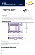
24 Volt Intelligent Thermostat (with 4.3” LCD Display)
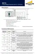
Wiring Diagram:
Hot
LC
AC
L5
L4
L3
L2
L1
24 VAC
high med
fan fan
relay relay relay
low
fan
CLG HTG
VALVE VALVE
Common
AQ1: Aquastat Connection - AQ2
AQ2: Aquastat Connection 2 - Jumper to AQ1
GND: Common for 0-10 Volt Output and Thermistor Input
T: Temperature Input - External Thermistor
CV: Control Voltage Output - 0-10 Volts
LC: Load Common, AC - COMM
AC: Load Hot, AC - 24 VAC
L5: Load 5 - Heat
L4: Load 4 - Cool / Compressor
L3: Load 3 - Low Fan Relay
L2: Load 2 - Medium Fan Relay / Cool 2*
L1: Load 1 - High Fan Relay / Reverse Valve / Heat 2*
*Depending on Thermostat Configuration
Conventional HVAC Systems:
Commonly Used
Wiring Terminal
Designators
Possible Signal
Names /
Functions
Possible Wire
Color
Comments
24VAC Com-
mon
From one side of the 24 VAC transformer, usually called the com-
mon side.
C
Black
Red
From the other side of the 24VAC transformer, usually called the
hot side. The thermostat may connect this terminal with W (call for
heat) or Y (call for cool), if RH and RC are not used / available. Some
thermostats also use this supply to power themselves.
R or V
24 VAC Hot
24VAC hot usu-
ally used for
call for heat
Functions as the source of power for the W terminal. Ther thermo-
stat usually connects this terminal with W when it calls for heat.
RH or 4
Red
24VAC hot usu-
ally used for
call for cool
Functionas as the source of power for the Y terminal. Ther thermo-
stat usually connects this terminal with Y when it calls for heat.
RC
G
Red
Activate blower
fan
Ther fan switch on the thermostat usually connects this terminal
with R when it is in the ON position.
Green
Ther thermostat usually connects this terminal with R or RG when it
calls for heat. Ther thermostat usually connects this terminal with
G when the fan switch is set to AUTO. Some thermostats require a
jumper from W to Y if a heat pump is used. Other thermostats might
use this as a second-stage heating. Sometimes W2 designates
auxilary heating in systems that use heat pumps.
W or W1 or W2
White
Call for heat
Call for cool
Ther thermostat usually connects this terminal with R or RC when it
calls for heat. The thermostat usually connects this terminal with G
when the fan switch is set to AUTO. Could also be for cooling of the
first-stage heating on a heat pump.
Y
Yellow
Varies
Outside air
temperature
display
Used to display the outside air temperaturre on some digital
thermostats.
S1 and S2

| General | Details |
|---|---|
| Name | MAGNUM FIRST M9-TS1 24 Volt Intelligent Thermostat Owner’s Manual |
| Make | MAGNUM FIRST |
| Language | English |
| Filetype | PDF (Download) |
| File size | 1.05 MB |
 (1 votes, average: 5.00 out of 5)
 Loading...


EPH CONTROLS eTRV Smart Radiator Thermostat Instruction Manual

OUELLET OTL221 Single Pole Mechanical Thermostat Instructions

DEVI 140F1134 Plug In Electronic Thermostat Installation Guide

EPH CONTROLS CP4B Battery Powered Programmable Thermostat User Guide

EUROTRONIC Programmable Energy-Saving Radiator Thermostat User Manual

SECURE H3747 Smart Programmable Thermostat Installation Guide

EVERBILT Electric Upper Thermostat Instructions

BEOK TGP53 Wifi Thermostat User Guide

BEOK TDR89 Zigbee Room Thermostat User Guide

hansgrohe 15384XXX RainSelect Thermostat Instruction Manual