
LATICRETE 0804-0402-TW Programmable LCD Thermostat Instruction Manual


™
Supply voltage:
Load amperage:
120/240 VAC - 50/60 Hz
Maximum15A - resistive load
40 to 105°F / 5 to 40°C
40 to 110°F / 5 to 45°C
Class A - 5 mA trip level
STRATA_HEAT
MANUAL DEL USUARIO
Suelo radiante Termostato programable
Modelo: 0804-0402-TW
Programmable LCD Thermostat User Manual
Temperature set point range:
Operating temperature range:
GFCI specification:
Model: 0804-0402-TW
1 YEAR WARRANTY
GENERAL USE AND OPERATION
DESCONECTE LA ALIMENTACIÓN DE RED EN LA PLACA ANTES DE PROCEDER
Para evitar el riesgo de descargas eléctricas y lesiones, desconecte toda la energía que
llegue al sistema de calefacción y al termostato en el tablero de servicio principal antes
de instalar el termostato. Todo el cableado debe cumplir con los códigos y ordenanzas
eléctricas locales y nacionales. La instalación debe ser realizada por personal cualificado.
INSTALACIÓN
1. Aflojepero no lo retire, el tornillo situado en la parte inferior de la cara del termostato. Levante la parte
inferior para separar la cara frontal del módulo de potencia trasero.
2. Complete el cableado de la fuente de alimentación y del calefactor tal y como se indica en la parte posterior
del módulo de potencia (mostrado a continuación). Nota: Diámetro del cable: 12 a 22 AWG
3. Conecte el sensor de suelo a IN/SNR del módulo de potencia.Nota: No importa qué cable del sensor va en
cada terminal.
4. Instale el módulo de potencia trasero en la caja del dispositivo utilizando tornillos de fijación.
5. Vuelva a colocar la cara del termostato en el módulo de potencia desde la parte superior presionando hacia
abajo hasta que el tornillo y el orificio queden alineados. Vuelva a apretar el tornillo para mantener la cara
del termostato en su sitio.
6. Vuelva a conectar la alimentación de red y pruebe la función GFCI antes de utilizar el termostato.
INTERRUPTOR DE CIRCUITO POR FALLO A TIERRA (GFCI)
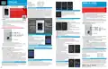
Depending on the selected mode, this thermostat controls your floor heating system using either a
manual (up/down only) setting, or an automatic weekly program, running in 4 or 2 stages per day,
7 days a week. The default weekly program will work for most people, however you can modify the
weekly program settings to suit your specific needs. This thermostat includes an adaptive function
where the thermostat begins heating or stops heating ahead of the next programmed event in order
to bring the room temperature to the set temperature of the next event time more efficiently. Please
note that when you turn the adaptive feature on for the first time, the thermostat will take a few
days to learn the precise on and off timing required. Always keep the air vents on the rear of the
Power Module clean & free from obstructions such as paint or silicone.
DISCONNECT MAIN POWER SUPPLY
AT THE BOARD BEFORE PROCEEDING
To avoid risk of electric shock and injury, disconnect all
power coming to the heater(s) and thermostat at the
main service panel before installing the thermostat.
All wiring must conform to local and national electrical
codes and ordinances. Installation must
ENERGY USE
Shows energy consumption based on the heating time
and power. The power figure (the total power of the
heaters your thermostat controls) is set in User Settings
> Power Set setting.
be carried out by qualified personnel.
USER SETTINGS
[Use the arrows at the bottom of the screen to scroll to other User Settings]
INSTALLATION
1. Loosen, but do not remove, the screw at the bottom of the thermostat Face.
GFCI RESET BUTTON
GFCI TEST BUTTON
Scan for additional
product information.
Set Time: Set the thermostat’s clock
2. Lift upwards from the bottom to separate the front Face from the rear Power Module.
3. Wire the main power supply and heater cables as indicated on the rear of the Power Module
(shown below).
Set Date: Set the thermostat’s date
Child Lock: Lock all keys to prevent the setting from
being changed.
(behind lens)
LED
TIME
ACTUAL TEMPERATURE
HEATING INDICATOR
■
Wire diameter: 12 to 22 AWG
4. Wire the floor sensor to IN/SNR of Power Module.
(Push/hold UP for 3s to unlock)
Unit: Set temperature unit - °F or °C
Power Set: Set the system power for Energy Use
calculation
MODE STATE
UP / DOWN BUTTONS
■
SET TEMPERATURE
NEXT EVENT INFO
It does not matter which sensor wire goes into which terminal.
CARGA - 120V
SUMINISTRO - CALIENTE 120V
DISCONNECT ALL POWER BEFORE INSTALLING THE THERMOSTAT
MODE BUTTON
SUMINISTRO - CALIENTE 120V / NEUTRO
CARGA - 120V / NEUTRO
Display Brightness: Set the screen brightness from
1-9
EDIT BUTTON
Language: Choose the thermostat language - English/Francais/Espanol
LOAD - 120V
SUPPLY - HOT 120V
Daylight Saving Time: When enabled, the thermostat adjusts automatically to daylight saving time
Set Backlight Delay: Choose how long (5-60s) the screen remains bright after the last screen press
Support: Shows support contact details
User Reset: Resets all users settings to factory default values
INSTALLER SETTINGS
Cable sensor
FUNCTIONS AND SETTINGS
Mode selection
This thermostat provides three operating modes:
Automatic mode: Follows the weekly program, adjusting the
temperature automatically.
SUPPLY - HOT 120V / NEUTRAL
LOAD - 120V / NEUTRAL
Este termostato termostato tiene un GFCI integrado para proteger a los usuarios de lesiones debidas a descargas eléctricas.
Es importante probar el funcionamiento del GFCI todos los meses siguiendo estos pasos:
1. Confirme que el termostato está encendido.
Adaptive Function:
2. Pulse y suelte (no mantenga pulsado) el botón de PRUEBA situado en la parte superior derecha del termostato:
ON - Thermostat will reach the scheduled temperature by the scheduled time
OFF - Thermostat will activate the scheduled temperature at the scheduled time;
Open Window: ON - Thermostat detects an open window (sudden temperature drop) and shuts off
heating temporarily to save energy
■
Sensor wire
Manual mode: Constantly maintains the manually set temperature.
Frost protection mode: Constantly maintains a pre-set temperature
between 41-59°F (5-15°C). This mode is used quickly set a
lower temperature, typically when you are on vacation.
OFF: Turns off all thermostat functions but remains powered.
TEMPORARY TEMPERATURE OVERRIDE
To temporarily increase or decrease the temperature when in Automatic mode, use UP/DOWN. The
temperature will return to the scheduled temperature at the next scheduled event.
EDIT SELECTION MENU
La función GFCI es normal si aparece una luz roja y "FALLO A TIERRA" en la pantalla.
La función GFCI defectuoso si no hay respuesta; póngase en contacto con el instalador o
electricista inmediatamente.
■
3. Si la función GFCI es normal, pulse el botón RÉINITIALISATION situado en la parte superior izquierda del
termostato. La luz roja debería apagarse y la pantalla debería volver al modo de funcionamiento normal.
5. Install the rear Power Module into the device box and using set screws.
6. Reattach the Face to the Power Module from the top by pressing down until the screw and hole
align. Re-tighten the screw to hold the Face in place.
Sensor Application: Choose which sensor is used to control the heating:
Room - Uses the built-in air sensor
Floor - Uses the floor probe
■
Si durante el uso normal la luz roja y "Fallo a tierra" compruebe si existe un fallo de conexión a tierra
pulsando el botón RÉINITIALISATION. Si el termostato no se restablece a la normalidad, significa que se ha
producido un fallo a tierra y se debe contactar inmediatamente con el instalador o electricista debe ponerse
en contacto inmediatamente con el instalador o electricista.
Si la luz roja se apaga pero la pantalla muestra el estado de apagado, se trata de un disparo molesto.
ESPECIFICACIONES Y CLASIFICACIÓN DEL TERMOSTATO
7. Reconnect the main power and test the GFCI function before using the thermostat.
Floor Protection - Uses the air sensor but is
limited by a maximum set floor sensor setting
■
GROUND FAULT CIRCUIT INTERRUPTER (GFCI)
(The maximum floor temperature setting is set
in the Floor Protection installer setting)
This thermostat has an integrated GFCI to protect users from injury due to electric shock.
It is important to test the GFCI function every month using these steps:
1. Confirm that the thermostat is powered on.
Este termostato termostato es un dispositivo de Clase II con aislamiento reforzado, y está diseñado para
controlar la calefacción eléctrica por suelo radiante según las especificaciones que se indican a continuación. La
especificación de la calefacción por suelo radiante debe coincidir con la tensión de alimentación y la carga total
combinada del sistema de calefacción no debe superar los 15 amperios.
Sensor Type: Choose the sensor type if not using
the supplied sensor
2. Press and release (do not hold) the TEST button on the top right of the thermostat:
Floor Temp. Calibration: Offset the displayed
temperature from the measured temperature
■
GFCI function is normal if a red light appears and Ground Fault message appears on the screen.
GFCI function is faulty if there is no response; contact your installer or electrician immediately.
3. If the GFCI function is normal, then press the RESET button on the top left of the thermostat. The
red light should turn off and the screen should return to normal operating mode.
Suministro tensión:
Amperaje de carga:
Rango de temperatura de consigna:
Rango de temperatura de funcionamiento:
Especificación GFCI:
120/240 VCA - 50/60 Hz
Máximo 15 A - carga resistiva
40 a 105°F / 5a 40°C
40 a 110°F / 5 a 45°C
Clase A - nivel de disparo de 5 mA
■
Room Temp. Calibration: Offset the displayed temperature from the measured temperature
Floor Protection: Set a maximum floor sensor limit - used if your flooring type has a maximum
allowed temperature (typically used for wood or vinyl)
Location: Choose Home for 4 events per day and Office for 2 events per day
Factory Reset: Reset the thermostat to factory
■
If during normal use the red light and GROUND FAULT message appear, you should check if the
ground fault is present by pressing the RESET button. If the thermostat does not reset to normal,
it means that ground fault has occurred and you contact your installer or electrician immediately.
USO GENERAL Y FUNCIONAMIENTO
Dependiendo del modo seleccionado, este termostato controla el sistema de calefacción por suelo radiante utilizando
un ajuste manual (sólo arriba/abajo) o un programa semanal automático, funcionando en 4 ó 2 etapas por día,
7 días a la semana. El programa semanal predeterminado funcionará para la mayoría de las personas, aunque los
ajustes del programa semanal pueden modificarse para adaptarse a necesidades específicas. Este termostato incluye
una función adaptativa en la que el termostato empieza a calentar o deja de calentar antes del siguiente evento
HEATING SCHEDULE
Assign seven days a week to the following two schedules:
settings, ALL settings will be reset.
■
If the red light turns off but the screen shows the shut-down status, it is nuisance tripping.
ROOM SENSOR FAILURE ALARM
7 Individual temperature and schedule settings for selected days
5+1+1 Set temperature for Monday to Friday with separate settings for Saturday and Sunday.
To set a schedule, select the days you wish to set, then choose the period, then set the desired start
time and temperature for the period. Repeat these steps until your schedule is complete.
THERMOSTAT SPECIFICATION & CLASSIFICATION
If the thermostat does not reset to normal after
being power-cycled (power to the thermostat turned
off and on), it means that the sensor has failed and
you contact your installer or electrician.
This thermostat is a Class II device with reinforced insulation, and is designed to control electrical floor
heating per the specifications below. The floor heating specification must match the supply voltage and
the total combined load of the heaters must not exceed 15 Amps.
n
LATICRETE International, Inc. One LATICRETE Park North, Bethany, CT 06524-3423 USA
n
n
DS-10209-0724 ©2024 LATICRETE International, Inc. All trademarks shown are the intellectual properties of their respective owners.
^See Data Sheet 230.13 for complete warranty information.


| General | Details |
|---|---|
| Name | LATICRETE 0804-0402-TW Programmable LCD Thermostat Instruction Manual |
| Make | LATICRETE |
| Language | English |
| Filetype | PDF (Download) |
| File size | 0.24 MB |
 (1 votes, average: 5.00 out of 5)
 Loading...

LATICRETE Strata Heat WiFi Thermostat Instruction Manual

Laticrete 0804-0402-TW Manual: Questions and Answers
What's the difference between Automatic and Manual mode on Laticrete 0804-0402-TW?
Automatic follows your weekly program and adjusts temperature automatically. Manual constantly maintains your manually set temperature.
| Mode | Behavior |
|---|---|
| Automatic | Follows weekly program, adjusts temperature automatically |
| Manual | Constantly maintains manually set temperature |
What do the UP and DOWN buttons do on Laticrete 0804-0402-TW?
In Automatic mode, they temporarily raise or lower the temperature until the next scheduled event. Instruction Manual, p. 1
What does 'Ground Fault' mean on Laticrete 0804-0402-TW display?
The integrated GFCI has detected an unsafe electrical condition. Press RESET to clear it. If it doesn't clear, contact your installer immediately. Instruction Manual, p. 1
Can I use Laticrete 0804-0402-TW with a floor sensor that's not the one supplied?
Yes. In Installer Settings, use Sensor Type to choose a different sensor if not using the supplied one. Instruction Manual, p. 1
How do I test the GFCI function on Laticrete 0804-0402-TW?
Test the GFCI every month following these steps.
- Confirm the thermostat is powered on.
- Press and release the TEST button on the top right.
- A red light and Ground Fault message should appear.
- Press the RESET button on the top left.
- The red light should turn off and the screen return to normal operating mode. Instruction Manual, p. 1
More Laticrete thermostat manuals

JUMO exTHERM-AT Explosion-Protected Surface-Mounted Thermostat Instruction Manual

Zehnder ComfoControl Ease Installation Guide

HONEYWELL RTH5160 Series Non-Programmable Thermostat Installation Guide

tuya BHT-005 Wifi Heating Thermostat User Manual

SmartLife ZBHTR20WT Zigbee Radiator Thermostat Installation Guide

EPH CONTROLS RDTP Recessed Programmable Thermostat Installation Guide

SALUS CONTROLS IT700 Smart Thermostat Instruction Manual

beok TGW60 Thermostat User Guide

EPH CONTROLS RFRB RF Room Thermostat Instruction Manual

COLDBUSTER MCD5 Programmable Thermostat User Manual