Home > InverterCool > InverterCool CPT100 2C Wi-Fi Thermostat Instruction Manual
InverterCool CPT100 2C Wi-Fi Thermostat Instruction Manual


CPT100
3H/2C Wi-Fi Thermostat
Installation Manual

| General | Details |
|---|---|
| Name | InverterCool CPT100 2C Wi-Fi Thermostat Instruction Manual |
| Make | InverterCool |
| Language | English |
| Filetype | PDF (Download) |
| File size | 0.3 MB |


InverterCool CPT100 2C Wi-Fi Thermostat Instruction Manual Overview
Summary of Contents
- Page 1: CPT100 3H/2C Wi-Fi thermostat Installation manual
- Page 2: Regulatory statements outline compliance with FCC rules. The device must not cause harmful interference and must accept any interference received. Modifications not approved by the responsible party may void the user's authority to operate the equipment. The equipment complies with Class B digital device limits designed to protect against harmful interference. Users should try to correct interference by reorienting the receiving antenna or increasing separation between equipment and receiver. The equipment complies with RF radiation exposure limits and should maintain a minimum distance of 20 centimeters from persons. This device adheres to Industry Canada license-exempt RSS standards. Operation is subject to conditions that the device must not cause interference and must accept any interference. The user is responsible for accepting any radio interference that may affect device operation. The device is compliant with applicable Industry Canada standards for license-exempt radio devices.
- Page 3: Safety instructions should be read carefully before installing and using the CPT100 Thermostat. This manual serves as a reference guide for installation, configuration, and maintenance. Follow all local regulations regarding thermostat installation or replacement. An authorized, qualified installer may be required. Do not connect any terminals to 110 VAC or 220 VAC supply voltage; the CPT100 Thermostat uses a 24 VAC power source. Avoid exposing the unit to voltage fluctuations of more than ±10%. Do not cover any vents on the thermostat or allow the unit to get wet. This device is intended for use in dry, closed living and office spaces. Do not place the thermostat in areas of excessive moisture or where relative humidity exceeds 90%. Avoid exposing the thermostat to temperatures below 14⁰F (-10⁰C) or above 140⁰F (60⁰C). Do not install the unit at altitudes over 6,500 feet (2,000 meters). Use a soft dry cloth for cleaning; do not use solvents or aggressive cleaning agents.
- Page 4: Using this manual provides essential instructions for operation. For the latest instructions, refer to the official website. Special attention boxes are used to highlight important safety concerns and operational information. Safety icons indicate conditions that may lead to severe personal injury or major property damage. Important information icons denote details necessary for the correct operation of the controls. Your benefit icons provide helpful installation or setup information.
- Page 5: Regulatory statements Safety instructions Using this manual In the box Installing the thermostat Tools Turn off power to HVAC system Determine wiring configuration Remove old thermostat Install mounting plate
- Page 6: In the box CPT100 thermostat with mounting plate wall plate (if required) mounting screws & anchors installation manual
- Page 7: Installing the thermostat requires specific tools. You may need a Phillips or flathead screwdriver, a power drill with a 3/16” bit, and a smartphone or camera for reference. There are five steps to installing the thermostat: Determine the wiring configuration. Remove the old thermostat. Determine if a wall plate is required to cover any openings or damage. Install the CPT100 base. Connect the wires. Attach the display. Turn off power to the HVAC system before starting the installation. Change the temperature setting to ensure the HVAC system is not operating when removing the old thermostat.
- Page 8: Determine wiring configuration If the CPT100 thermostat is being installed in a new system or if wiring changes are intended, refer to Appendix A for the wiring configurations and skip to install mounting plate. When replacing a thermostat and replicating the wiring of the existing thermostat is desired on the CPT100, the following applies. Remove the old thermostat to expose the wiring terminals. Photograph the wiring for reference or use the table below to note the wire colors. Use the wire color record to note the wire color and function of each wire. If the terminals of the existing thermostat are unmarked, determine the wire functions for each color wire at the appliance.
- Page 9: Page 9
- Page 10: Remove the old thermostat from the wall, taking care not to allow the wiring to fall inside the wall. Wrap wires around a pencil or similar object to prevent them from falling into the wall void. The CPT100 thermostat is not compatible with supply voltages above 30 VAC. If the old thermostat is connected with thick wire and wire nuts or voltages higher than 30 VAC are noted on the connections, do not install the thermostat.
- Page 11: Install mounting plate with wall plate, if required. Use the included wall anchors and screws to attach the mounting plate to the wall. Make sure the wires run through the center opening. To cover paint or screw holes on the wall behind the thermostat, insert the wall plate between the mounting plate and the wall. Both plates are secured with the same screws.
- Page 12: Attach wiring: To insert a wire into a terminal, flip up the locking tab and slide the wire into the socket directly above the corresponding label. Insert each wire as required for the desired appliance. Once each wire is inserted, flip the tab down to lock it in position. Pull gently on each wire after locking the tab is closed to be sure the wire is secure. A factory supplied jumper is supplied between RC and RH. This should be removed in two transformer systems.
- Page 13: Attach display to mounting plate. Line up sockets in the back of the thermostat with the posts on the wall plate and snap it into place. Make sure the connector pins are not bent and wires do not interfere with the thermostat engagement. The thermostat must be fully seated on the wall plate to operate correctly.
- Page 14: Turn on power to the HVAC system. Go to the furnace switch or breaker box and turn the HVAC system back on. When the CPT100 is first powered or if a factory reset is performed, the boot sequence will be displayed. The last screen displays the thermostat model and firmware version number. When the text thermostat is ready to connect with the smart device application, it begins scrolling across the text field. Download the InverterCool Smart Controller application on your iOS or Android device. After downloading the application, follow the steps in the InverterCool Mobile Application Guide. Setup starts or manual setup, please see page 18-Parameter Settings.
- Page 15: Screen display and controls include an alphanumeric text display. Indicators include schedule override, fan, cooling mode, off mode, setpoint, auto cooling/heating mode, schedule running, heating mode, Wi-Fi, emergency heat, and key lock. Functions for increasing and decreasing values are available. Mode selection and fan speed selection are also part of the controls. Temperature can be displayed in Fahrenheit or Celsius. Room temperature is indicated on the display.
- Page 16: Parameter settings require certified personnel for adjustments. Access the Parameter Settings menu by pressing Mode + Fan for over 3 seconds. Use the Fan button to navigate to submenus or save selections. Press Mode to move up one menu without saving. Menu options can be navigated using designated buttons. Settings include HVAC type, reversing valve, and number of stages. Options for heating sources include gas or electric. Time zone settings are available for various regions. Time and date can be set manually or automatically when connected to the internet. Hour format can be set to either 12 or 24-hour format.
- Page 17: Continue the form on the previous page. Parameter Name NETWORK Key Description Settings STATUS Cloud Connection Status Wi-Fi Network Name SSID IP Address MAC Address Device IP Address Device MAC Address RSSI RESET Wi-Fi Signal Strength Reset Network Settings Enable Frost Protection Adjust Temperature Display FROST Temp Cal Set ON/OFF differential Set Differential between heating and cooling Reset Thermostat to Factory Defaults DEADBAND FACTORY RESET Additional Keypad shortcuts Press Mode + Fan briefly to toggle temperature display between ⁰F and ⁰C Press briefly to toggle between Lock and Unlock keypad Press Mode for longer than 3 seconds to toggle between “Run Schedule” or “Non-Programmable” To Factory Reset and return the device to “Mobile Setup” mode Press Mode + Fan for longer than 3 seconds – display shows SYSTEM Press button – display scroll FACTORY RESET Press Fan – display shows NO Press or – display shows YES Press Fan – the thermostat will display WAIT then reboot and display will scroll MOBILE SETUP
- Page 18: Specifications include temperature units in °C or °F, with an operating range of 32 to 122°F (0 to 50°C). The device operates in a humidity range of 5 to 90% relative humidity (non-condensing) at temperatures from 14 to 140°F (-10 to 60°C). It supports communications via 802.11 b/g/n on the 2.4 GHz band and Bluetooth v4.2 BR/EDR and BLE for commissioning. AC power requirements are 18-30 VAC at RC and C terminals, with 5 relay outputs rated for 1A at 18-30 VAC. The dimensions of the device are 3.9” x 4.2” x 0.9” (10.0cm x 10.6cm x 2.3cm). The weight of the device is 0.6 lbs. (297 g). Compliance includes FCC and Industry Canada regulations. The product comes with a 5-year limited warranty. The CPT100-1 wire extender module is listed as a compatible device. Specifications are subject to change without notice.
- Page 19: Warranty period is five years from the date of purchase. The product is warranted to be free of defects in materials and workmanship under normal use. InverterCool will repair or replace defective products at no charge during the warranty period. Repaired or replaced devices are warranted for the remainder of the original warranty period or ninety days, whichever is longer. The warranty does not cover removal or reinstallation costs. It does not apply to products that have been modified, improperly maintained, or subjected to unusual stress or misuse. This warranty is the only express warranty provided by InverterCool for the product. Implied warranties are limited to the warranty period or the shortest period allowed by law. InverterCool is not liable for any loss or damage resulting from any breach of warranty. Some states may not allow exclusions or limitations on incidental or consequential damages.
- Page 20: Warranty information states that no oral or written information will modify or extend the warranty. If any term is deemed illegal or unenforceable, it does not affect the remaining terms. The customer's sole remedy under this limited warranty is product repair or replacement. If a product under warranty is defective, the customer may contact the seller for a replacement after verification. Alternatively, the customer can contact InverterCool Service to determine eligibility for a replacement. A credit card may be required for a replacement shipped before the return of the defective device. This warranty provides specific legal rights, and additional rights may vary by jurisdiction. For questions regarding the warranty, customers can write to InverterCool, Inc.
- Page 21: Wiring diagrams for CPT100 thermostat terminal reference are provided. The document includes terminal references for non-heat pump and heat pump configurations. Key terminals include RC for 24 VAC power for cooling and RH for 24 VAC power for heating. C is used for 24 VAC common, with a note to use CPT100-1Wire extender if C-wire is not available. G is designated for the fan. Y1 represents the first stage of cooling, while Y2 is for the second stage of cooling. W1/OB is for the first stage of heating, and W2/AX is for the second stage of heating. L indicates auxiliary or emergency heat. Check/fault input is also included in the terminal references.
- Page 22: InverterCool heat pump system. 2nd stage. Compressor. Auxiliary heat. 1st stage. Reversing valve. 24VAC common. Dehumidifier. Fan.
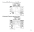
- Page 23: Conventional single transformer heat and cool system. Conventional two transformer heat and cool system.
- Page 24: The manufacturer reserves the rights to change specifications or designs without notice.

Honeywell T841A,B Easy-To-SeeTM Heat Pump Thermostat Instruction Manual

KCONTR K6HWIFI WiFi Smart Thermostat User Guide

AVATTO WT598 1T1 Smart Thermostat

EPH Controls TRFPi2 Programmable RF Thermostat Instruction Manual

EcoNet RETST800SYS Smart Thermostat User Guide

degrii THM Edge Cutting Smart Thermostat User Guide

EMMETI U9330000 Zona Smart Thermostat Instruction Manual

Danfoss ECtemp 530 Electronic Thermostat Installation Guide

Danfoss RET-MD Electronic Intelligent Dial Setting Thermostat Installation Guide

Honeywell Home TH2110U4004 Programmable Thermostat Installation Guide