Home > Honeywell > Honeywell VisionPRO TH8000 Series Touch Screen Programmable Thermostat User Guide
Honeywell VisionPRO TH8000 Series Touch Screen Programmable Thermostat User Guide

Installation
Guide
®
VisionPRO TH8000 Series
Touch-screen Programmable Thermostat
This manual covers the following models
• TH8110U: For 1 Heat/1 Cool systems
• TH8320U: For up to 3 Heat/2 Cool systems
• TH8321U: For up to 3 Heat/2 Cool systems with dehumidification
(Pull thermostat from wallplate and turn over to find model number)
• Heat only — two-wire systems,
System Types
• Gas, oil, or electric heat with air
power to open and close zone
valves (Series 20), and normally
open zone valves
conditioning
• Warm air, hot water,
highefficiency furnaces, heat
pumps, steam, gravity
• Heat only with fan
• Cool only
• 750 mV heating systems
This thermostat contains a Lithium battery which may contain Perchlorate material.
Perchlorate Material—special handling may apply,
Need Help?
or call Honeywell Customer Care toll-free at 1-800-468-1502
® U.S. Registered Trademark.
Copyright © 2012 Honeywell International Inc.
All rights reserved.
69-2693-01
firealarmresources.com

| General | Details |
|---|---|
| Name | Honeywell VisionPRO TH8000 Series Touch Screen Programmable Thermostat User Guide |
| Make | Honeywell |
| Language | English |
| Filetype | PDF (Download) |
| File size | 0.26 MB |


Honeywell T6 Pro Programmable Thermostat User Manual

Honeywell D1-528 Direct Thermostat Installation Guide

Honeywell FocusPRO P200 Programmable Thermostat User Guide

Honeywell RCHT8610WF Series Smart Thermostat Installation Guide

Honeywell T9 Smart Thermostat Installation Guide

Honeywell TH2320WF4011 FocusPRO Smart S200 Series Thermostat User Guide

Honeywell TL116A Thermostat Installation Guide

T10 Pro Smart Thermostat with Redlink Room Sensor

Honeywell TH6320WF2003 Lyric T6 Pro Wi-Fi Programmable Thermostat User Guide

Honeywell RLV3100 Digital Thermostat Installation Guide

Honeywell VisionPRO TH8000 Series Touch Screen Programmable Thermostat User Guide Overview
Summary of Contents
- Page 1: Installation guide for VisionPRO TH8000 series touch-screen programmable thermostat. This manual covers the following models: TH8110U, TH8320U, TH8321U. System types include gas, oil, or electric heat with air conditioning, warm air, hot water, high-efficiency furnaces, heat pumps, steam, and gravity. The thermostat contains a lithium battery which may contain perchlorate material. Special handling may apply for perchlorate material. For assistance with this product, visit the Honeywell customer support website or call customer care. Copyright © 2012 Honeywell International Inc. All rights reserved.
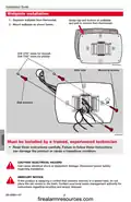
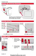
- Page 2: Installation guide for wallplate installation includes important steps and warnings. Separate the wallplate from the thermostat. Mount the wallplate as shown in the instructions. Drill 3/16” holes for drywall and 7/32” holes for plaster. Installation must be performed by a trained, experienced technician. Read the instructions carefully to avoid damage or hazardous conditions. Disconnect power before beginning installation to prevent electrical shock or equipment damage. If replacing a control with mercury, do not dispose of it in the trash. Contact local waste management for recycling and proper disposal instructions.
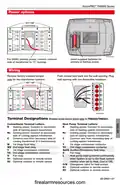
- Page 3: Power options Insert supplied batteries for primary or backup power. For 24VAC primary power, connect common side of transformer to “C” terminal. Remove factory-installed jumper only for two-transformer systems. Push excess wire back into the wall opening. Plug wall opening with non-flammable insulation. Terminal designations apply only to TH8320/TH8321. Conventional terminal letters include R, C, W, Y, and G. Heat pump terminal letters include Rc, C, W, Y, and G. Auxiliary/Emergency heat relay is designated as Aux/E. Optional outdoor or remote sensors are designated as S1 and S2.
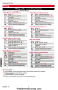
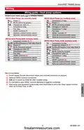
- Page 4: Installation guide Wiring guide—conventional systems Shaded areas below apply only to TH8320/TH8321. 1H/1C system (1 transformer) 1H/1C system (2 transformers) Heat only system Cool only system 2H/2C system (1 transformer) 2H/2C system (2 transformers) Provide disconnect means and overload protection as required. Remove jumper for 2-transformer systems.
- Page 5: Wiring guide—heat pump systems Shaded areas below apply only to TH8320/TH8321. 1H/1C Heat Pump (no auxiliary heat) 2H/2C Heat Pump (no auxiliary heat) 2H/1C Heat Pump (with auxiliary heat) 3H/2C Heat Pump (with auxiliary heat) Power supply. Provide disconnect means and overload protection as required. Optional 24VAC common connection. Changeover valve set to control as either O or B in installer setup. If L terminal is used, 24VAC common (terminal C) must be connected.
- Page 6: Installation guide provides steps for mounting the thermostat and setting the date and time. To mount the thermostat, remove the tab and align the pins on the back with the slots in the wallplate. Press the button to set the date, time, month, and year. Press DONE to save changes and exit. Installer setup requires pressing and holding specific buttons until the display changes. Change settings as required according to the instructions provided.
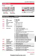
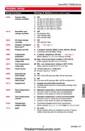
- Page 7: VisionPRO TH8000 Series Installer setup Press DONE to exit & save settings. Setup functions Settings & Options (factory default in bold) Shaded areas below apply only to TH8320/TH8321. Schedule format 7-day programming System type Fan control (heating)
- Page 8: Installation guide Installer setup Setup functions Settings & options (factory default in bold) Shaded areas below apply only to TH8320/TH8321. First stage heat cycle rate (CPH) Gas or oil furnaces of less than 90% efficiency Steam or gravity systems Hot water systems & furnaces of 90%+ efficiency Electric furnaces Manual/Auto changeover Temperature display
- Page 9: VisionPRO TH8000 Series Installer setup Setup functions Settings & options (factory default in bold) Furnace filter change reminder Humidifier pad change reminder UV lamp change reminder Adaptive Intelligent Recovery™ Program periods Temperature display offset
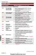
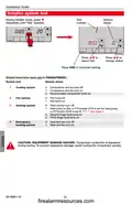
- Page 10: Installation guide During installer setup, press repeatedly until “Test” appears. Press to select test. Press to change status. Press DONE to terminate testing. Shaded areas below apply only to TH8320/TH8321. Compressor and fan turn off. Compressor and fan turn on. Heat turns on (fan on if Function 0170 is set for heat pump). CAUTION: Equipment damage hazard. Compressor protection is bypassed during testing.
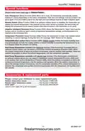
- Page 11: VisionPRO TH8000 Series Auto Changeover: The thermostat automatically selects heating or cooling depending on the indoor temperature. Remote Sensor: The thermostat can display outside temperature with an optional outdoor sensor. Adaptive Intelligent Recovery: The thermostat learns how long the furnace and air conditioner take to reach programmed temperature settings. Compressor Protection: Forces the compressor to wait before restarting to prevent damage. Dehumidification Control: Monitors indoor humidity and activates the cooling system to reduce humidity. Heat Pump Temperature Lockout (with fossil-fuel backup): Selects a compressor lockout temperature based on outdoor temperature. Heat Pump Temperature Lockouts (with electric heat backup): Allows selection of compressor and auxiliary heat lockout temperatures. Accessories & Replacement Parts: Contact your distributor to order replacement parts. Outdoor temperature sensor: Part Number C7089U1006. Remote indoor temperature sensor: Part Number C7189U1005.
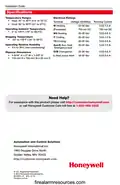
- Page 12: Installation guide Specifications Temperature ranges Heat: 40° to 90°F (4.5° to 32°C) Cool: 50° to 99°F (10° to 37°C) Operating ambient temperature: 0° to 120°F (-18° to 48.9°C) Shipping temperature: -30° to 150°F (-34° to 66°C) Operating relative humidity: 5% to 90% (non-condensing) Physical dimensions: 4-9/16” H x 6” W x 1-3/8” D Need help?

InverterCool CPT100 2C Wi-Fi Thermostat Instruction Manual
tuya TRV603 Smart WiFi Radiator Thermostat Instruction Manual

Immax neo LITE 07534L Smart Thermostat for Underfloor Heating User Manual

DAIKIN S21 One Lite Smart Thermostat User Guide
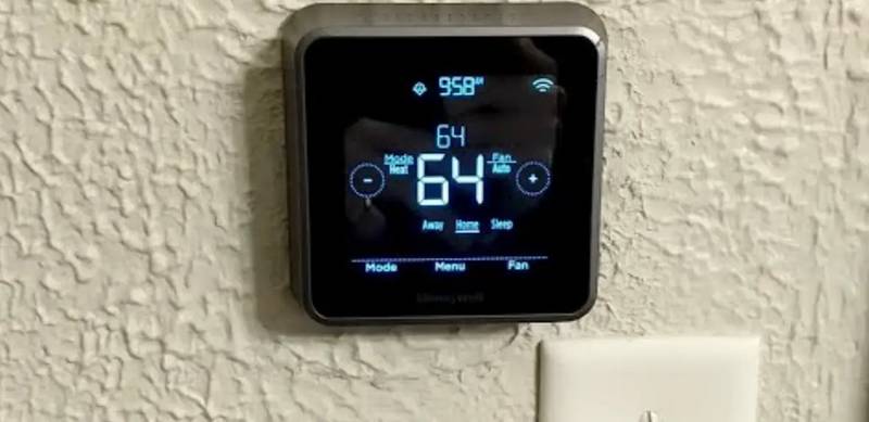
Honeywell Home RTH Series T5 Smart Thermostat Installation Guide
ENGO CONTROLS E901RF Wireless Programmable Thermostat User Guide
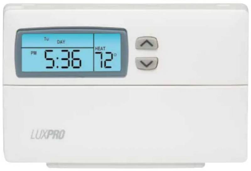
LUX PSP511Ca Programmable Thermostat Instruction Manual

LUX TH10 Heating Only Mercury FREE Manual Thermostat Instruction Manual

homematic IP HmIP-eTRV-E Series Radiator Thermostat Evo Installation Guide

nVent RAYCHEM Elexant 3500i Electronic Thermostat Installation Guide