Home > GENERAL LIFE > GENERAL LIFE FH100 Underfloor Heating Thermostat User Manual
GENERAL LIFE FH100 Underfloor Heating Thermostat User Manual


ROOM THERMOSTAT PLACEMENT
WIRING DIAGRAM FOR ACTUATOR
ENGLISH
Place your Room Thermostat in a room you use frequently in your
living space. For example; like the hall or living room of your home.
Avoid installing the Room Thermostat in places where there is a lot of
air circulation, such as at the doorway or by the window. Also, do not
place it close to heating units (heater core, fireplace, etc.) and in direct
sunlight. We recommend that the room thermostat is placed at a
height of 150cmfrom thefloor.
N
L
L1
N1
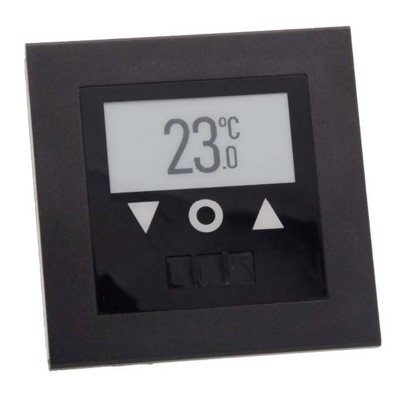
UNDERFLOOR HEATING THERMOSTAT
generallife.com.tr
FH100 USER MANUAL
min. 20 cm
GENERAL SPECIFICATIONS
FH100 is
UNDERFLOOR HEATING THERMOSTAT
a
floor heating room thermostat. User provides more
comfortable and affordable heating by setting needed room
temperature.
SensitiveTemperatureMeasurement
Wired Connection
ACTUATOR
ON/ OFFControl
ROOM THERMOSTAT WORKING PRINCIPLE
FH100
USER MANUAL
As soon as you energize your Room Thermostat, it will start working.
Your Room Thermostat measures the temperature of the
environment it is in every 5 seconds. If the ambient temperature rises
0.5 degrees above the temperature you set, your Room Thermostat
turns off the heating unit, and if it falls below 0.5 degrees, it turns on
theheating unit.
FH100 AND EQUIPMENTS
230V AC
FH100 Room Thermostat
Dowels and
Screws
WIRING DIAGRAM FOR WIRING CENTER
If the floor sensor measures temperature above 28°C, it turns off the
heating unit. The floor sensor operating sensitivityis ±1°C.*
Thus, it is ensured that the ambient temperature remains within a
certain range.
N
L
L1
N1
*Externalfloor sensor is only activewhen itis connected.
TECHNICAL DATA
Note: If a floor sensor is installed with Room Thermostat, only
GENERAL Life floor sensor should be installed. Otherwise, the
product willbe out of warranty.
Dimensions ( H / L / W )
Operating Current
Relay NO Switching Current
85.7mm / 85.7mm / 33.5mm
230V AC
7A (240VAC – Resistive load)
10A (120VAC – Resistive load)
0.1oC
ROOM THERMOSTAT WIRING DIAGRAM
Temperature Measurement
Accuracy
0.5oC
1
2
3
4
Operating Temperature Range
Operating Temperature
Storage Temperature
(5oC) – (30oC)
(-10oC) – (+50oC)
(-20oC) – (+60oC)
WIRING
CENTER
ROOM THERMOSTAT
230V AC
Indicator LED
Set Button
WARNING!
Operations related to the control panel, heating unit or electrical
installation must be carried out by persons with professional
qualifications.
5
N
L
NTC
L1
N1
WARNING!
6
RoomThermostatIndicator LED Descriptions
LED light is on
LED light is off
Heating unit is working
The assembly of product
Heating unit is not working
should be done according to
the image above.
For electrical connection,
please see diagram 5.
Should not be used in case
the usage of a wiring center.
generallife.com.tr
1
2
3

| General | Details |
|---|---|
| Name | GENERAL LIFE FH100 Underfloor Heating Thermostat User Manual |
| Make | GENERAL LIFE |
| Language | English |
| Filetype | PDF (Download) |
| File size | 1.97 MB |


GENERAL LIFE HT330S RF Room Thermostat User Manual

GENERAL LIFE FH103S Underfloor Heating Thermostat User Manual

GENERAL LIFE HT250 RF Digital Room Thermostat User Manual

GENERAL LIFE FH104S Underfloor Heating Thermostat User Manual

GENERAL LIFE ARUNA 302S Digital Room Thermostat User Manual

GENERAL LIFE FH250S Underfloor Heating Thermostat User Manual

GENERAL LIFE FC220 Digital Fan Coil Thermostat User Manual

GENERAL LIFE HT220S RF Digital Room Thermostat User Manual

GENERAL LIFE 270S RF Room Thermostat User Manual

GENERAL LIFE 270 Wireless Room Thermostat User Manual

GENERAL LIFE FH100 Underfloor Heating Thermostat User Manual Overview
Summary of Contents
- Page 1: Room thermostat placement is important for effective heating. Avoid installing the room thermostat in areas with high air circulation or near heating units. The recommended height for placement is 150 cm from the floor. The FH100 is a floor heating room thermostat that allows users to set the desired room temperature. It features sensitive temperature measurement and wired connection. The room thermostat measures ambient temperature every 5 seconds to control the heating unit. If the floor sensor measures above 28°C, it will turn off the heating unit. Only the General Life floor sensor should be installed with the room thermostat to maintain warranty. Operations related to the control panel and electrical installation must be performed by qualified personnel. LED indicators show the status of the heating unit and the assembly of the product.
- Page 2: Warranty certificate Declaration of conformity Devices and their apparatus are out of warranty if they are beaten, broken, or scratched by the customer. Damages resulting from the use of devices and apparatus belonging to other brands and models without the approval of the manufacturer are not covered by the warranty. Battery leakage and errors due to rust, oxidation, and liquid contact by working in acidic/humid environments are not covered by the warranty. When the product is not used for a long period (more than 15 days), remove the batteries. Otherwise, malfunctions that occur are out of warranty. Damages that may occur during the transportation of devices and apparatus are not covered by the warranty. The warranty period starts from the invoice date and is warranted against manufacturing defects for 2 years. The repair of the devices and apparatus covered by the warranty is carried out in our company factory. In case of malfunctioning of the devices and apparatus whose warranty period continues, it is tested in our company whether the malfunction is caused by a customer or manufacturer fault.

sinope TH1500ZB Smart Double Pole Thermostat Installation Guide
AuVerte SC801 SpiritCatcher Thermostat Owner’s Manual

heatmiser neoStat-e Electric Floor Heating Thermostat Instructions

vtech W960 E-Smart Wireless Thermostat User Manual

ENGO CONTROLS E901RF Series Programmable Thermostat User Guide

Chytre Vypinace HC-T020-EWF Series Thermostat Owner’s Manual

Honeywell TH6320U2008 Pro Programmable Thermostat Installation Guide

Honeywell RLV4305 Programmable Thermostat Owner’s Manual

ELKO ep TER-4 Double Thermostat Owner’s Manual

SALUS TS600 Remote-Only Thermostat User Guide