
DOOR D4004 Wireless Thermostat User Guide
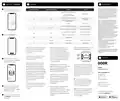


Add Device To DOOR App
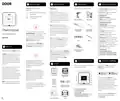
Installation
FCC Statement
F
H
G
This device complies with part 15 of the FCC
Rules. Operation is subject to the following two
conditions: (1) This device may not cause
harmful interference, and (2) this device must
accept any interference received, including
interference that may cause undesired
operation. Any Changes or modifications not
expressly approved by the party responsible
for compliance could void the user's authority
to operate the equipment.
1
In the Home screen of the app, tap on
the card located in the top right.
Thermostat Terminal
Typical Wire Designations
Function
Remarks
Non-heat Pump: Stage 1 Cool Mode
Y1
Y1
Typically Yellow
Heat Pump: Stage 1
Compressor ON/OFF Control
Non-heat Pump: Stage 2 Cool Mode
Typically Yellow or
Light Blue
Y2
G
Y2
G
Note: This equipment has been tested and
found to comply with the limits for a Class B
digital device, pursuant to part 15 of the FCC
Rules. These limits are designed to provide
reasonable protection against harmful
interference in a residential installation. This
equipment generates uses and can radiate
radio frequency energy and, if not installed and
used in accordance with the instructions, may
cause harmful interference to radio
communications. However, there is no
guarantee that interference will not occur in a
particular installation. If this equipment does
cause harmful interference to radio or
television reception, which can be determined
by turning the equipment off and on, the user
is encouraged to try to correct the interfer-
ence by one or more of the following
measures:
Heat Pump: Stage 2 Compressor
ON/OFF Control
Typically Green
Fan Relay
Non-heat Pump: Stage 1 Heat Mode
Heat Pump: Stage 1 Heat or Cool Modde
According to O/B Setting
Typically White or Brown
W1, W, O/B
W1
Non-Heat Pump: Stage 2 Heat Mode
Heat Pump: Stage 2 Cool Mode
Auxiliary Heat
Typically White or Brown
According to O/B Setting
W2
W2
2
Tap on the "Add device" icon.
AUX
AUX
- Reorient or relocate the receiving antenna.
- Increase the separation between the
equipment and receiver.
- Connect the equipment into an outlet on a
circuit different from that to which the
receiver is connected.
- Consult the dealer or an experienced
radio/TV technician for help.
Typically Cyan, See Note 1.
Typically Red
C
R
C OR COM
R, RC, RH
24VAC Common
24VAC Power
1. Refer to the chart above, match up your
thermostat wires with their matching
screw terminal on the Thermostat
terminal strip.
5. Mount the new back plate to the
If you set the HP/GAS switch to GAS, the
valve will only energize for heating.
The device has been evaluated to meet general
RF exposure requirement. The device can be
used in portable exposure condition without
restriction.
wall, using the appropriate method, for
example, with the supplied drywall
anchors. Position the plate, to cover the
hole in the wall, and check the level of the
plate, as needed. Do not overtighten the
mounting screws, as this will warp the
back plate, adversely impacting the
thermostat operation.
HP GA
W1
W2
Y1
Y2
C
AUX
G
2. Turn off power, as required, to ensure
there are no energized wires at the
thermostat location.
R
O
B
Contact Us
I
3
Approve access to your phone’s
3. Before making any changes to the
thermostat wiring, it is important to
identify the individual wires and their
functions using the supplied labels (or
masking tape, etc). Label each wire with
9. Gently push the thermostat down onto
the back plate. You may hear an audible
click, as it snaps into place. Observe the
rear thermostat sides, near the wall, to
ensure there are no uneven gaps between
the plate and the thermostat. Gently tug on
the thermostat, to ensure it does not
come loose.
6. Terminate each conductor on its
respective screw terminal. You will need
Support
to ensure a good connection.
Door Technologies, Inc.
1220 N Price Rd
STE 2
thermostat ("C", "R" etcetera). It may also
help to have a picture of the wiring on
the existing thermostat, in case a label
falls off or if you need to reinstall the
existing thermostat.
7. Refer to the rear of the Thermostat.
Set the HP/GAS slide switch to HP for
heat pump systems otherwise to GAS
You can change the switch setting with
a small screwdriver, pencil or
10. Turn on power to the unit. The
Thermostat display should immediately
turn on. If not, double-check your wire
terminations, power-off the unit and
correct any mistakes, as needed.
Olivette, MO 63132
Copyright © 2024
4. Remove your existing thermostat and
back plate from the wall. Use care to not
allow the cable to fall into the hole in
the wall.
similar object.
Door Technologies, Inc.
All rights reserved.
4
Hold the phone over the QR code
so that the code appears in the
next
8. If you set the HP/GAS switch to HP,
set the O/B slide switch to O for
energizing the reversing valve on heating
(cold climates) or B for energizing the
reversing valve on cooling (hot climates)
operation.
Note:
or one labeled COM or COMMON. The
Thermostat will not function without
a C wire (or C wire adapter, as
previously noted).
steps will be displayed.
download the DOOR App:
5
Follow the on-screen instructions in
the DOOR App, which will guide you
step by step.

| General | Details |
|---|---|
| Name | DOOR D4004 Wireless Thermostat User Guide |
| Make | DOOR |
| Language | English |
| Filetype | PDF (Download) |
| File size | 0.5 MB |
 (1 votes, average: 5.00 out of 5)
 Loading...


OUELLET OTL221 Single Pole Mechanical Thermostat Instructions

TRANE XR202 Programmable Thermostat User Guide

ENGO CONTROLS EFAN-230W Fan Coil Thermostat User Guide

GENERAL LIFE FH250 Floor Heating Room Thermostat User Manual

Danfoss ECtemp Smart Intelligent Electronic Timer Thermostat Installation Guide

hawco AC2-5 Two Stage Thermostat Instruction Manual

SIEMENS RS485 Flush Mounted Room Thermostat User Manual

COMPUTHERM Q20 Programmable Digital Room Thermostat Instruction Manual

OSCAR OS20 LCD Thermostat Instruction Manual

Honeywell Home X1N Non Programmable Thermostat Installation Guide