terneo BeeRT Digital Thermostat Instruction Manual

Outlet of heat
transfer medium
from boiler
External
IN THE BOX
Thermostat
It is necessary for the temperature controller to switch
theꢀcurrent to no more than 2/3 of the maximum current
specified in the specification. If the current exceeds this
value, the load must be connected through a contactor
(magnetic actuator, power relay), which is optimized
forꢀthis current (Wiring 1).
programmer
smart control of heating
Аir sensor
1 piece
2 piece
Temperature sensor
with connecting wire
Feed
sensor
BeeRT
Technical data sheet and
installation and operation manual
and warranty card
L
N
In order to protect from short circuits and excess power
events appearance in the load circuit, it is necessary
toꢀinstall an automatic circuit breaker (CB), which should
be installed in the live wire break, as shown on Wiring 1.
1 piece
1 piece
Technical data sheet and
1
3
installation and operation manual
1
2
3
4
5
6
t°
t°
А
1
The packing box
°С
Boiler
Terneo BeeRT thermostat is designed to control electric
heating systems based on electrode or heating element
boilers with the ability to control the operation of the pump
and monitor its serviceability. terneo BeeRT also allows
you to connect an external programmer for maximum
comfort and energy savings.
fee
«fe
«return» hyste
pump overrun
d
r
eturn
1
3
4
А
1
e
d»
hysteresis
r
e
si
s
The thermostat terminals are designed for a wire
withꢀsection not more than 2,5 mm2. To reduce
theꢀmechanical loads on the terminals it is desirable
toꢀuse aꢀsoft wire. Theꢀwires are tightened in the terminals
using aꢀscrewdriver with a blade width no more than
3ꢀmm. Theꢀterminals should be tighten with torque
0,5ꢀN·m. Use of aluminum is not desirable.
Theꢀscrewdriver with a blade width more than 3 mm can
cause mechanical damage to the terminals. This may
result in the loss of right for warranty.
t
i
m
e
2
А2
terneo BeeRT
А2
WIRING
7
8
9
10
11
12
2
4
Return
sensor
Thermostat supports two types of sensors: analog sensor
(R10) or digital sensor (D18).
Thermostat ensures comfortable and safe operation of
boiler due to regulation of «feed» and «return»
temperature. The heating starts when the «return»
temperature drops to hysteresis value and is turned off
when the «feed» or «return» temperature reaches the set
value.
Connect the analog red «feed» temperature sensor
toꢀterminals 1 and 2. Digital sensor is connected to
terminalꢀ1 using red (or yellow) wire and to terminal 2 using
white wire.
Inlet of heat
transfer medium
to boiler
Wiring 1. Connecting a single-phase boiler
using a power relay
If necessary, it is allowed to shorten and expand sensor
connecting wires (separate cable not more than 40 m).
Power wires should not be placed near connection wire
ofꢀsensor otherwise they may cause interference.
Connect the analog blue «return» temperature sensor to
terminals 5 and 6. Digital sensor is connected to terminal 5
using red (or yellow) wire and to terminal 6 using white
wire.
Non-volatile thermostat storage saves all settings
inꢀtheꢀevent of a power outage.
Outlet of heat
IMPORTANT. Before the installation and operation
of the device, please read by the end of this document.
This will help to avoid possible danger, mistakes and
misunderstandings.
External
programmer
transfer medium
Be sure to select the type of sensor in the functional menu
of the thermostat when using a digital sensor (see Table 1,
menu item «Selecting the type of sensor»). If sensors are
connected incorrectly or one of them fails, when the
thermostat is turned on, eights are displayed onꢀthe screen
for 5 seconds, and then «OC» or «SC» (see page 7).
from boiler
WARRANTY TERMS
Аir sensor
Feed sensor
The warranty for terneo devices is valid for 36 months
from the date of sale, provided that the instructions
areꢀfollowed. The warranty period for products without
aꢀwarranty certificate is counted from the date
ofꢀproduction.
TECHNICAL DATA
L1 L2 L3 N
The supply voltage (230 V ±10 %, 50 Hz) is supplied
toꢀterminals 9 (phase, L) and 10 (zero, N).
1
3
5
7
Limits of regulation of «feed»
Limits of regulation of «return»
15–95 °С, step 1 °С
5–90 °С, step 0,1 °С
1–30 °С, step 0,1
1
2
3
4
5
6
t°
t°
А1
Terminals 7 and 8 (voltage-free relay contacts) are used
toꢀcontrol the pump.
°С
If your device is not working properly, we recommend that
you first read the section «Possible problems». If you
cannot find an answer, contact Service Center. In most
cases, these actions resolve all issues.
ЕSС 463
Ith: 50A
Ui: 440V~
feed
return
«
fe
e
e
d
»
h
ysteresis
turn» hyste sis
ump overrun
A1
A2
1
3
5
7
«
r
r
t
e
im
230V~
50 Hz
p
e
Temperature hysteresis
Pump overrun time
Terminals 11 and 12 (voltage-free relay contacts) are used
to control the boiler heater.
2
4
6
8
terneo BeeRT
А2
7
8
9
10
11
12
2
4
6
8
10–60 sec
2 х 16 А
If you continue to have issues with the device, please
send it to a Service Center or to the store where you
purchased the device. If your device is defective due
toꢀour fault, we will repair or replace it under warranty
within 14 business days.
Return
sensor
The contact group of the temperature programmer
isꢀconnected to terminals 3 and 4.
Maximum load current
(for category AC-1)
Rated load capacity (for category AC-1)
Input voltage
2 х 3 000 VА
230 V ±10 %
0,26 kg ±10 %
52 × 90 × 67 mm
R10 in heat shrink
4 m
INSTALL AND CHECK THE LOAD before installing
and connecting the thermostat.
Inlet of heat
transfer medium
to boiler
Please see the full text of the warranty and the data you
need to send to your Service Center on the website
aꢀwarranty case, please, contact the General distributor
inꢀyour area.
Weight in the complete set
Overall dimensions (w × h × d)
Temperature sensor
POWER OF AUTOMATICS, POWER RELAY,
magnetic starter should be chosen based on
maximum power of the boiler.
Wiring 2. Connecting the automation of a 3-phase boiler
The length of the sensor
connected cable
SERVICE CENTER CONTACT
+38 (091) 481-91-81
FOR THE OPERATION OF THE PUMP AND
THEꢀBOILER, CONNECT APPROPRIATE PHASES
TO THE CONTROL RELAYS of BeeRT for switching,
since the relay contacts do not have a galvanic
connection with the power supply circuits, that is, the
relays used in the thermostat have a «dry normally
open contact» (see Wirings 1, 2).
INSTALLATION
Viber WhatsApp Telegram
Number combinations
under heat, at least
50 000 cycles
The thermostat is designed for indoor installation.
Theꢀingress risk of moisture or liquid into the place of
installation must be minimized. The ambient temperature
during installation must be between –5 ... + 45 °C.
Theꢀinstallation height of the thermostat should
beꢀinꢀtheꢀrange 0,4...1,7 m above the floor level.
Number of combinations without
heating, no less than
20 000 000 cycles
WARRANTY CARD
Сonnection
no more than 2,5 mm²
IP20
serial №:
date of sale:
Degree of protection GOST14254
The thermostat should be mounted in a special cabinet,
which allows accessible installation and operation.
Theꢀcabinet must be equipped with a standard 35 mm
mounting rail (DIN-rail). The temperature controller has
width of three standard 18 mm modules.
a seller, a seal:
place of a seal
an owner contact
for a service center:
1
2
3

| General | Details |
|---|---|
| Name | terneo BeeRT Digital Thermostat Instruction Manual |
| Make | terneo |
| Language | English |
| Filetype | PDF (Download) |
| File size | 0.3 MB |

terneo rzx Smart Thermostat User Manual
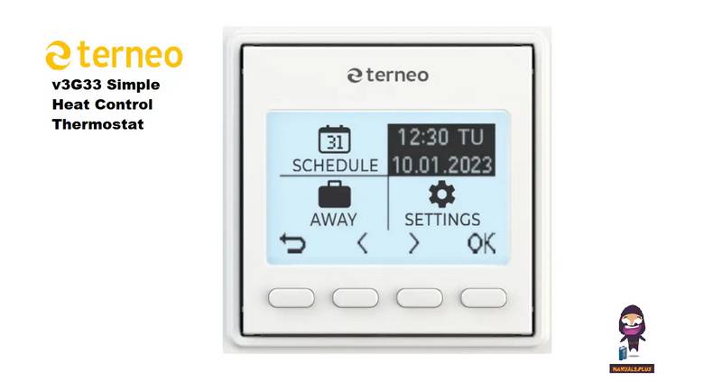
terneo v3G33 Simple Heat Control Thermostat Instruction Manual

terneo bx Smart Thermostat Instruction Manual

terneo BeeRT Digital Thermostat Instruction Manual Overview
Summary of Contents
- Page 1: Outlet of heat transfer medium from boiler The terneo BeeRT thermostat is designed to control electric heating systems based on electrode or heating element boilers with the ability to control the operation of the pump and monitor its serviceability. It is necessary for the temperature controller to switch the current to no more than 2/3 of the maximum current specified in the specification. To protect from short circuits and excess power events, it is necessary to install an automatic circuit breaker. The thermostat supports two types of sensors: analog sensor (R10) or digital sensor (D18). The heating starts when the return temperature drops to hysteresis value and is turned off when the feed or return temperature reaches the set value. Non-volatile thermostat storage saves all settings in the event of a power outage. Before the installation and operation of the device, please read by the end of this document. The warranty for terneo devices is valid for 36 months from the date of sale, provided that the instructions are followed. The thermostat is designed for indoor installation, and the ambient temperature during installation must be between –5 ... + 45 °C. The thermostat should be mounted in a special cabinet, which allows accessible installation and operation.
- Page 2: Exploitation After the end of its service life, the product must be disposed of in accordance with applicable law. Operation principle of terneo BeeRT thermostat with external programmer The feed temperature is the temperature of the coolant at the outlet of the boiler. The programmer controls the heating system based on set schedule. For the operation of the boiler, set the main parameters: the temperature and hysteresis of return and feed. To reset the factory settings, hold the three buttons at the same time for more than 12 sec until dEF message appears on the screen. Safety instructions Connection of the device must be done by a qualified electrician. Do not connect 230 V mains voltage instead of the sensor. Button blocking (child and public protection) Do not immerse the sensor with a connecting wire in the liquid medium.

sinope TH1124NP Non Programmable Thermostat for Electric Heating Owner’s Manual

Danfoss 015G3090 React Radiator Thermostat Installation Guide

ESi ESRTP6C, ESRTP6CW Centro Prog Room Thermostat User Guide

Wiser CCTFR6100 Radiator Thermostat Instruction Manual

KETOTEK F0155 WiFi Thermostat Instruction Manual

Tio TEVO Smart RF Wireless Thermostat User Manual

SALUS SQ610RF Smart Thermostat Instruction Manual

REPTO R3300030 Smart Thermostat Instruction Manual

sensi 1F76U-22WFB Series Lite Smart Thermostat Installation Guide

ENSTO ECO16BTD Combination Thermostat Instruction Manual