Honeywell RTH2510/RTH2410 Thermostat Installation Guide


This is a legacy product document
supported by Resideo. It is no
longer manufactured
Quick Installation Guide
RTH2510/RTH2410
Programmable Thermostat
69-2421ES-03

| General | Details |
|---|---|
| Name | Honeywell RTH2510/RTH2410 Thermostat Installation Guide |
| Make | Honeywell |
| Language | English |
| Filetype | PDF (Download) |
| File size | 0.61 MB |


Honeywell T6 Pro Programmable Thermostat User Manual

Honeywell D1-528 Direct Thermostat Installation Guide

Honeywell FocusPRO P200 Programmable Thermostat User Guide

Honeywell RCHT8610WF Series Smart Thermostat Installation Guide

Honeywell T9 Smart Thermostat Installation Guide

Honeywell TH2320WF4011 FocusPRO Smart S200 Series Thermostat User Guide

Honeywell TL116A Thermostat Installation Guide

T10 Pro Smart Thermostat with Redlink Room Sensor

Honeywell TH6320WF2003 Lyric T6 Pro Wi-Fi Programmable Thermostat User Guide

Honeywell RTH9580 Wi-Fi Color Touchscreen Programmable Thermostat User Guide

Honeywell RTH2510/RTH2410 Thermostat Installation Guide Overview
Summary of Contents
- Page 1: This is a legacy product document supported by Resideo. It is no longer manufactured. Quick installation guide for RTH2510/RTH2410 programmable thermostat.
- Page 2: Quick installation guide This thermostat is compatible with the following systems: Gas, oil or electric furnace Central air conditioner Hot water system with or without pump Millivolt system Central heating and cooling system Heat pump without auxiliary/backup heat Heat pump with auxiliary/backup heat This thermostat cannot be used on multistage systems.
- Page 3: Turn off power to heating/cooling system.
- Page 4: Quick installation guide Remove old thermostat but leave wallplate with wires attached. Do not put your old thermostat in the trash if it contains mercury in a sealed tube. Contact your local waste management authority for instructions regarding recycling and proper disposal. Do not remove wallplate yet.
- Page 5: Identify wires. If any wires are not attached to your old thermostat or are attached to a terminal marked C or C1, they will not be connected to your new thermostat. Wrap the bare metal end of each of these wires with electrical tape, so it cannot touch and short other wires. Do not use non-connected wires. Do not use C or C1 wires. Identify and label each wire. Ignore wire colors: use terminal screw designations to identify wires. Disconnect wires and remove the old wallplate only after all wires are labeled. Wrap the wires around a pencil to prevent them from falling through the wall opening.
- Page 6: Quick installation guide Loosen the locking screw at the bottom of the thermostat. Separate the thermostat from the wallplate. Position the wallplate against the wall and mark hole positions with a pencil. Drill holes at the marked positions and insert supplied wall anchors. Pass the wires through the large opening located at the bottom center of the wallplate. Secure the wallplate to the wall with supplied mounting screws. Connect the wires to the terminals.
- Page 7: Connect wires for conventional systems. Match each labeled wire with the terminal having the same letter. Remove jumper if you have both R and RC wires. Loosen the terminal screws using a screwdriver, insert the wires, then tighten the screws. Push any excess wire back into the wall opening. Labels don’t match? See page 6. For heat pumps with auxiliary/backup heat, see pages 7-8. Call for wiring assistance.
- Page 8: Quick installation guide Connect wires Conventional systems Remove jumper between R and RC if you have wires on both R and RC. Do not use C, C1, or X wire. Do not use B wire if you already have O wire. Wrap bare end of wire with electrical tape. Place a jumper (piece of wire) between Y and W/AUX if you are using a heat pump without auxiliary/backup heat.
- Page 9: Connect wires for heat pump systems with auxiliary or backup heat. Match each labeled wire with the terminal having the same letter. Loosen the terminal screws, insert the wires, then tighten the screws. Push any excess wire back into the wall opening. If labels don’t match, refer to page 8.
- Page 10: Quick installation guide Connect wires: Heat pump Systems with auxiliary/backup heat Leave jumper in place, connecting R and RC. This thermostat cannot be used if your old thermostat had any two of the following wires R, RC, V, or VR. Do not use C or X wire. Do not use B wire if you already have O wire. Wrap bare end of wire with electrical tape. If your old thermostat had separate O and B wires, wrap the B wire in electrical tape and do not connect. If your old thermostat had Y1, W1 and W2 wires, stop now and contact a qualified contractor for help.
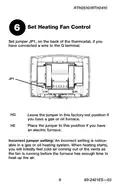
- Page 11: Set heating fan control. Set jumper JP1 on the back of the thermostat if you have connected a wire to the G terminal. Leave the jumper in the factory-set position if you have a gas or oil furnace. Place the jumper in this position if you have an electric furnace. An incorrect jumper setting is noticeable in a gas or oil heating system. When heating starts, you will initially feel cold air coming out of the vents. The fan runs before the furnace has enough time to heat up the air.
- Page 12: Quick installation guide Set heat pump reversing valve Set jumper JP2 on the back of the thermostat if you have a heat pump. Leave the jumper in the factory-set position if you have connected O wire to the O/B terminal. Place the jumper to this position if you have connected B wire to the O/B terminal. Incorrect jumper setting will reverse heat pump operation.
- Page 13: Install batteries on the back of the thermostat. Align the two brackets on the top of the thermostat with the corresponding slots on the top of the wallplate. Push the thermostat against the wallplate. Tighten the screw at the bottom of the thermostat. Turn power back on at the heating/cooling system.
- Page 14: Advanced installation System setup Temperature display Time display format Heating cycles per hour Compressor protection Early start System startup Customer assistance Limited warranty
- Page 15: RTH2510/RTH2410 user thermostat Follow the procedure below to personalize and configure the thermostat according to the heating/cooling system. Press and hold the s and t buttons simultaneously for three seconds until the display appears. Press the s or t button to change the option. Press the s and t buttons simultaneously for one second to advance to the next function. When the last function is displayed, press the s and t buttons to save any changes and exit the menu. If you do not press any button for 60 seconds while in the setup menu, the thermostat automatically saves any changes made and exits the menu. At any time you can save the changes and exit by pressing the Run button.
- Page 16: Advanced installation guide Press the s or t button to select Fahrenheit or Celsius temperature display. Fahrenheit temperature display (°F) Celsius temperature display (°C) When correct setting is selected, press both s and t to display next function.
- Page 17: RTH2510/RTH2410 Press the s or t button to select 12-hour display or 24-hour display. When correct setting is selected, press both s and t to display next function.
- Page 18: Advanced installation guide Make sure system switch is in the heat position. Press the s or t button to select your heating system and optimize its operation. 2 to 6 cycles per hour. Use this setting if you have a standard gas or oil furnace that is less than 90% efficient. Use this setting if you have a steam or gravity heat system. Use this setting if you have a hot water system or a gas furnace of greater than 90% efficiency. Use this setting if you have a standard gas or oil furnace that is less than 90% efficient. Use this setting if you have any type of electric heating system. When correct setting is selected, press both s and t to display next function.
- Page 19: Compressor protection is an important feature to prevent damage. The compressor must wait 5 minutes before restarting after shutdown. During the wait time, the messages Cool On or Heat On will flash on the screen. When the wait time is over, the flashing message stops and the compressor turns on. To select compressor protection, press the s or t button. The options for compressor protection are 1 (On) and 0 (Off). When the correct setting is selected, press both s and t to display the next function.
- Page 20: Advanced installation guide Early start allows the thermostat to “learn” how long your furnace or air conditioner takes to reach the set temperature. Simply program the desired times and desired temperatures into the schedule. The thermostat will determine when to activate heating or cooling so that the desired temperature is attained at the desired time. When correct setting is selected, press both s and t to display next function.
- Page 21: RTH2510/RTH2410 thermostat Press the s or t button to select system startup. Conventional system (1H1C) Heat pump system with auxiliary/backup heat (2H1C) When correct setting is selected, press the s and t buttons to save any changes and exit the menu.
- Page 22: Advanced installation guide Customer assistance For assistance with this product, please visit the Honeywell website or call Honeywell Customer Care toll-free.
- Page 23: One-year limited warranty Honeywell warrants this product, excluding battery, to be free from defects in the workmanship or materials, under normal use and service, for a period of one (1) year from the date of purchase by the consumer. If at any time during the warranty period the product is determined to be defective or malfunctions, Honeywell shall repair or replace it. This warranty does not cover removal or reinstallation costs. Honeywell’s sole responsibility shall be to repair or replace the product within the terms stated above. Honeywell shall not be liable for any loss or damage of any kind, including any incidental or consequential damages. This warranty is the only express warranty Honeywell makes on this product. The duration of any implied warranties, including the warranties of merchantability and fitness for a particular purpose, is hereby limited to the one-year duration of this warranty. This warranty gives you specific legal rights, and you may have other rights which vary from state to state. If you have any questions concerning this warranty, please write Honeywell Customer Relations.
- Page 24: Do not place your old thermostat in the trash if it contains mercury in a sealed tube. Contact your local waste management authority for instructions regarding recycling and proper disposal. To avoid possible compressor damage, do not run air conditioner if the outside temperature drops below 50°F (10°C). Automation and Control Solutions Honeywell International Inc. Printed in U.S.A.
- Page 25: Guía de instalación rápida Termostato programable
- Page 26: Guía de instalación rápida Identifique el tipo de sistema Este termostato es compatible con los siguientes sistemas: Calefactor a gas, aceite o eléctrico Aire acondicionado central Sistema a agua caliente con o sin bomba Sistema de milivoltios Calefacción y aire acondicionado centrales Bomba de calor sin calefacción auxiliar Bomba de calor con calefacción auxiliar Este termostato no puede usarse en sistemas multietapas
- Page 27: Desconecte la alimentación en el sistema de calefacción/refrigeración.
- Page 28: Guía de instalación rápida Remueva su viejo termostato Retire el termostato existente pero deje la placa de montaje con los cables adheridos. Advertencia sobre el mercurio: No arroje el viejo termostato a la basura si contiene mercurio en un tubo sellado. Comuníquese con la autoridad local de gestión de desechos para reciclarlo o eliminarlo adecuadamente. No retirar la placa mural todavía.
- Page 29: Identifique los cables. Si en el viejo termostato hubiera cables no conectados o conectados a un terminal marcado C o C1, estos cables no se usarán con el nuevo termostato. Recubra el extremo de metal desnudo de cada uno con cinta aisladora para que no puedan tocarse y producir un corto circuito. No use los cables no conectados. No use los cables C o C1. Identifique y etiquete cada cable. Ignore los colores de los cables: use las designaciones de los tornillos terminales para identificar los cables. Desconecte los cables y retire la vieja placa mural sólo después de haber etiquetado los cables. Enrosque los cables en torno a un lápiz para impedirles caer dentro del agujero de la pared.
- Page 30: Guía de instalación rápida Instalar la nueva placa mural Aflojar los tornillos de la base del termostato. El tornillo está cautivo y no se lo puede retirar de la base. Separar el termostato de la placa mural como se indica en la Figura 1. Colocar la placa mural contra la pared y marcar la posición de los agujeros con un lápiz. La nivelación se hace por razones estéticas solamente y no afectará el rendimiento del termostato. Perforar los agujeros en las posiciones marcadas e introducir los tacos de anclaje provistos para los tornillos. Pasar los cables por la gran abertura ubicada en la parte inferior, en el centro de la placa mural, como se ve en la Figura 2. Fijar la placa mural a la pared con los tornillos provistos, como en la Figura 3. Conectar los cables a los terminales.
- Page 31: RTH2510/RTH2410 Conecte los cables: Sistemas convencionales (conexión típica) Hacer coincidir cada cable etiquetado con el terminal de la misma letra. Retire el puente si hay cables R, Y, RC. Aflojar los tornillos del terminal con un destornillador, introducir los cables y reajustar los tornillos. Empujar el exceso de cables en el agujero de la pared. ¿Las etiquetas no coinciden? Ver la pág. 6. ¿Bomba de calor con calefacción auxiliar? Ver las págs. 7-8.
- Page 32: Guía de instalación rápida Conecte los cables Sistemas convencionales Si los cables están conectados con los terminales R, Y, RC, retire el puente. No usar los cables C, C1 o X. No usar el cable B si ya existe un cable O. Envolver el extremo desnudo de los cables con cinta aisladora. Poner un puente (trozo de cable) entre Y y W/AUX si se usa una bomba de calor sin calefacción auxiliar.
- Page 33: RTH2510/RTH2410 Conecte los cables: Sistemas de bombas de calor con calefactor auxiliar (conexión típica) Hacer coincidir cada cable etiquetado con el terminal de la misma letra. Aflujar los tornillos del terminal con un destornillador, introducir los cables y reajustar los tornillos. Empujar el exceso de cables en el agujero de la pared. ¿Las etiquetas no coinciden? Ver la página 8.
- Page 34: Guía de instalación rápida Conecte los cables: Sistemas de bombas de calor con calefactor auxiliar (conexión alternativa) Deje el empalme en lugar, entre terminales de R y RC. No puede usarse este termostato si el viejo termostato tuviera dos de los siguientes cables: R, RC, V o VR. No usar los cables C o X. No usar el cable B si ya hay un cable O. Envolver el extremo desnudo con cinta aisladora. No usar el cable L. Envolver el extremo desnudo con cinta aisladora. Si su termostato existente tenía cables O y B separados, envuelva el cable B en cinta aislante y no lo conecte. Si su termostato existente tenía cables Y1, W1 y W2, ahora pare y entre en contacto con un contratista para la ayuda. Si el viejo termostato tiene cables E y AUX (o cables alternativos), conectar ambos cables al terminal AUX.
- Page 35: Ajuste el control del ventilador. Ajuste el puente JP1, que está en la parte de atrás del termostato, si se conectó un cable al terminal G. Deje el puente en este ajuste de fábrica en el caso de una estufa a gas o a aceite. Ponga el puente en esta posición en el caso de una estufa eléctrica. Ajuste incorrecto del puente: un ajuste incorrecto es evidente en un sistema de gas o de aceite. Cuando la calefacción se encienda saldrá aire frío de las rejillas. El ventilador se puso en marcha antes de que la estufa pudiera calentar el aire.
- Page 36: Guía de instalación rápida Ajuste de la válvula de inversión Ajustar el puente JP2, en la parte de atrás del termostato, en el caso de una bomba de calor. Dejar el puente en este ajuste de fábrica si hay un cable O conectado al terminal O/B. Poner el puente en esta posición si hay un cable B conectado al terminal O/B. Ajuste incorrecto del puente: el funcionamiento de la bomba de calor estará invertido.
- Page 37: Instalación de las pilas y del termostato. Instalar 2 pilas AAA en la parte de atrás del termostato. Alinear las dos lengüetas de la parte superior del termostato con las ranuras correspondientes de la parte superior de la placa mural. Empujar el termostato contra la placa mural. Ajustar el tornillo en la parte inferior del termostato. Volver a conectar el sistema de calefacción/aire acondicionado.
- Page 38: Guía de instalación avanzada Cómo cambiar la configuración Visor de la temperatura Formato de la hora Ciclos de calefacción por hora Protección del compresor Encendido anticipado Configuración del sistema Asistencia al cliente Garantía limitada
- Page 39: El procedimiento a continuación permite personalizar y configurar el termostato según el sistema de calefacción/enfriamiento. Presionar los botones s y t al mismo tiempo (3 seg.) hasta que se vea lo que se indica en la ilustración. Presionar s o t para cambiar de opción. Presionar s y t al mismo tiempo por un segundo para ir a la función siguiente. Cuando haya aparecido en pantalla la última función, presionar s y t para salvaguardar los cambios y salir del menú. Si no se presiona ningún botón durante 60 segundos mientras esté abierto el menú de configuración, el termostato salvaguarda los cambios automáticamente y sale del menú. En cualquier momento se pueden salvaguardar los cambios y salir del menú presionando el botón Run.
- Page 40: Guía de instalación avanzada Presione los botones s o t para optar entre visualizar la temperatura en grados Fahrenheit o en grados Celsius. Visualización de la temperatura en Fahrenheit (°F) Visualización de la temperatura en Centígrados (°C) Cuando haya elegido la configuración correcta, presione s y t para mostrar la función siguiente.
- Page 41: RTH2510/RTH2410 thermostat Press the buttons s or t to choose between displaying 12-hour or 24-hour format. 12-hour display 24-hour display When you have selected the correct setting, press s and t to show the next function.
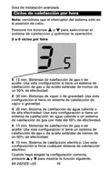
- Page 42: Guía de instalación avanzada Nota: cerciórese que el interruptor del sistema esté en la posición de calor. Presione los botones s o t para seleccionar el sistema de calefacción y optimizar la operación. Sistemas de calefacción de gas o de aceite: Use esta configuración si tiene un sistema de calefacción de gas o de aceite estándar de menos de un 90% de efectividad. Sistemas de vapor o de gravedad: Use esta configuración si tiene un sistema de calefacción de vapor o gravedad. Sistema de calefacción de agua caliente o de alta efectividad: Use esta configuración si tiene un sistema de calefacción de agua caliente o un sistema de calefacción de gas con más del 90% de efectividad. Sistema de calefacción eléctrico: Use esta configuración si tiene cualquier sistema de calefacción eléctrico. Cuando haya elegido la configuración correcta, presione s y t para mostrar la función siguiente.
- Page 43: RTH2510/RTH2410 Protección del compresor: El compresor puede dañarse si se pusiera en marcha enseguida después de haberse detenido. Esta función lo obliga a esperar 5 minutos antes de ponerse en marcha nuevamente, mientras los mensajes Cool On o Heat On parpadean en la pantalla. Cuando el lapso de seguridad finalice, el mensaje dejará de parpadear y el compresor se activará. Cuando haya elegido la configuración correcta, presione s y t para mostrar la función siguiente.
- Page 44: Guía de instalación avanzada La función encendido anticipado permite que el termostato “aprenda” cuánto le lleva a la estufa o al aire acondicionado para cumplir con la hora y la temperatura del horario. El termostato determina cuándo activar la calefacción o el enfriamiento para que la temperatura deseada se alcance a la hora deseada. Cuando haya elegido la configuración correcta, presione s y t para mostrar la función siguiente.
- Page 45: RTH2510/RTH2410 Configuración del sistema: Sistema convencional (1H1C) Bomba de calor con calefacción auxiliar (2H1C) Cuando haya elegido la configuración correcta, presionar s y t para salvaguardar los cambios y salir del menú.
- Page 46: Guía de instalación avanzada Si necesita asistencia, visite o llame al número gratuito de atención al cliente de Honeywell.
- Page 47: Honeywell garantiza este producto, a excepción de la batería, por el término de un (1) año contra cualquier defecto de fabricación o de los materiales, a partir de la fecha de compra por parte del consumidor. Si en cualquier momento durante el período de garantía se verifica que el producto tiene un defecto o que funciona mal, Honeywell lo reparará o reemplazará (a elección de Honeywell). Esta garantía no cubre los costos de extracción o reinstalación. La única responsabilidad de Honeywell será reparar o reemplazar el producto dentro de los plazos establecidos anteriormente. Honeywell no responderá por la pérdida o daño de ningún tipo, incluido el daño incidental o indirecto derivado, directa o indirectamente, del incumplimiento de las garantías. La presente garantía es la única garantía expresa que Honeywell proporciona respecto de este producto. La duración de las garantías implícitas, incluidas las garantías de comerciabilidad y aptitud para un objetivo particular, está limitada a la duración de un año de la presente garantía. Esta garantía le brinda derechos legales específicos, y usted podrá tener otros derechos que varían según el estado. Si tiene preguntas sobre la presente garantía, sírvase escribir a Honeywell Customer Relations. Algunos estados no permiten la exclusión o limitación del daño incidental o indirecto, entonces, esta limitación puede no resultar aplicable a su caso.
- Page 48: Aviso de mercurio: No arroje su viejo termostato a la basura si contiene mercurio en un tubo sellado. Comuníquese con la autoridad local de disposición de desechos para recibir instrucciones sobre reciclado y eliminación correcta. Precaución: Para evitar posibles daños al compresor, no utilice el aire acondicionado si la temperatura externa es inferior a 50 ºF (10 ºC).

ecobee M5A Smart Wi-Fi Thermostat User Guide

DIMPLEX ML2TA 2KW Convector Heater With Thermostat Instruction Manual

Unisenza Plus Stats Wired and Wireless Thermostat Instruction Manual
STELPRO UT202NP Series Non-Programmable Electric Thermostat Owner’s Manual

BROUWLAND Brew Monk Fermenter Digital Thermostat Instruction Manual

GENERAL LIFE MITRA 260S RF Digital Room Thermostat User Manual

OJ ELECTRONICS MWD5-1999-UAC3 Voice Control Wi-Fi Thermostat Instructions

LuxPro PSPLV512d Programmable Heating Thermostat Instruction Manual

Simx UT-M1 Ultecon Thermostat Instruction Manual

Honeywell Home FocusPRO 200 Series Programmable Thermostat Installation Guide